Sony hcd a 490 service manual

This is the 71 pages manual for sony hcd a 490 service manual.
Read or download the pdf for free. If you want to contribute, please upload pdfs to audioservicemanuals.wetransfer.com.

Page: 1 / 71
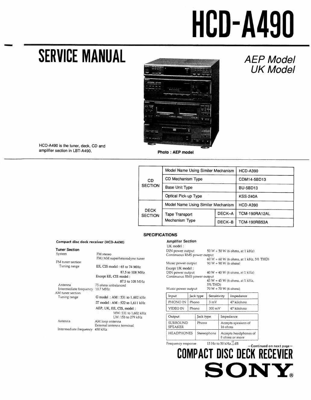
sony hcd a 490 service manual

Extracted text from sony hcd a 490 service manual (Ocr-read)


Page 2

Cassette deck Section
Recording system
Frequency response

4-track 2-channel stereo

DOLBY NR OFF

With Sony Type II cassette
40 Hz to 14 kHz (:3 (13)

With Sony Type 1 cassette
40 Hz to 13 kHz (:3 dB)

Wow and flutter . W. PEAKtOZii. (DIN)

CD player Section

Laser Semiconductor laser
Wavelength 780 - 790 nm
Frequency response 2 Hz to 20 kHz :05 dB
Signal-to-noise ratio More than 93 dB

More than 90 dB
Less than 0.005% (1 kHz)
More than 90 dB (1 kHz)

Dynamic range
Harmonic distortion
Channel separation

General
Power requirements Except UK model : 220 - 230 V AC. 50/60 Hz
UK model : 240 V AC, SOHZ
Except UK model : 150 W
UK model: 130 W
Mass Approx. 11.3 kg (24 lb 15 oz)
Dimensions Approx. 355 x 425 x 355 mm
(14 x16/ x 14 inches)
(w/h/d, including projections)

Power consumption

Supplied accessories

45-r/min adaptor (1)
Remote commander RM-S-ill (1)
FM wire antenna (1)
(Except G modal)

AM loop antenna (1)
Batteries Sony SUM-3 (NS) (2)
Note

EE : East European model
G German model
IT : italian model

Dolby noise reduction manufactured under license irorn
Dolby Laboratories Licensing Corporation.
DOLBY and the double-D symbol DC] are trademarks of
Dolby Laboratories Licensing Corporation.

Notes on chip component replacement

- Never reuse a disconnected chip component.

' Notice that the minus side of a tantalum capacitor may be
damaged by heat.

Fiexibie Circuit Board Repairing

- Keep the temperature of the soldering iron around 270 °C during
repairing.

0 Do not touch the soldering iron on the same conductor of the
circuit board (within 3 times),

0 Be careful not to apply force on the conductor when soldering or
unsoldering.

SAFETYARELATED COMPONENT WARNING

COMPONENTS IDENTIFIED BY MARK A OR DOTTED
LINE WITH MARK A ON THE SCHEMATIC DIAGRAMS
AND IN THE PARTS LIST ARE CRITICAL TO SAFE
OPERATION. REPLACE THESE COMPONENTS WITH
SONY PARTS WHOSE PART NUMBERS APPEAR AS
SHOWN IN THIS MANUAL OR IN SUPPLEMENTS PUB-
LISHED BY SONY.

MODEL IDENTIFICATION
-- BACK PANEL -

___-__..__.__________

F

88

4-642-744-11 : AEP Model
4~642~744-21 : AEP Model
4-642r744-31 : AEP Model
4-642-744-41 : German Model

4-642-74451 : Italian Model
4-642-744-6} : East European, CIS Model
4-642-744-71 : UK Model

4-642~744-81 : AEP Model

This appliance is classified as a CLASS 1 LASER product.
The CLASS 1 LASER PRODUCT MARKING is located on
the rear exterion

CLASS 1 LASER PRODUCT
LUOKAN I LASERLAITE

KLASS I LASERAPPARAT

Laser component in this product is capable of emitting
radiation exceeding the limit for Class 1.

The following caution label is located inside the unit.

-m.so-_e use: Maw-Em 1min can
CAUTION AvOlD EXPOSURE IOIEAu

usmuo useasnuuwc vro Wm:
ADVARSEL SIKKEMEWFBRVDERE ER UDE AF FUNKYIDN
smug roe swim

; mnrsssn u sownuxivus EONVYETIAESSA
om MI'IIINA usznwenm

'LASERSYRALING w: DENNA DEL AR ovwm
'ocx svnnnzn AR uuoevmu

ADVARSEL , usmis useismmnc MR DEKSEL Arne:
uwm EKsPoNERinc. so: srmEN