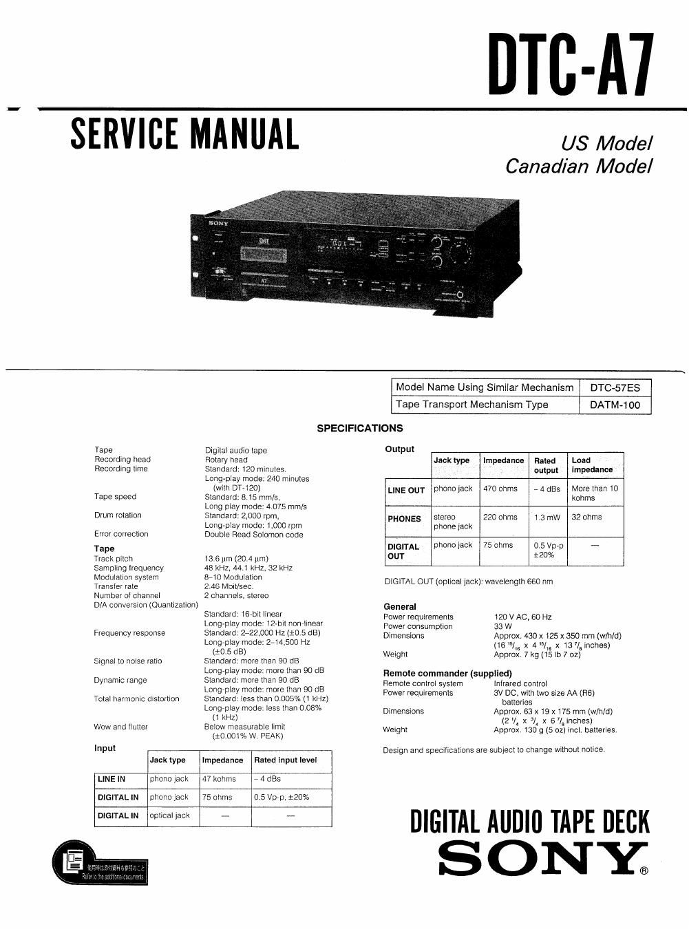
Sony dtc a 7 service manual
This is the 59 pages manual for sony dtc a 7 service manual.
Read or download the pdf for free. If you want to contribute, please upload pdfs to audioservicemanuals.wetransfer.com.
Extracted text from sony dtc a 7 service manual (Ocr-read)
Page 1
DTC-A'I
SERVICE MANUAL us Model
Canadian Mode/
Model Name Using Similar Mechanism DTC-57ES
Tape Transport Mechanism Type DATM-100
SPECIFICATIONS
Tape Digital audio tape Output
Recording head Rotary head Jack type Impedance Rated Load
Recording time Standard: 120 minules. output impedance
Long-play mode: 240 minutes
(with D1120) LINE OUT phone jack 470 ohms - 4 st More than 10
Tape speed Standard: 815 mm/s. kohms
Long play mode: 4.075 mm/s
Drurn rotation Standard: 2.000 rpm, PHONES stereo 220 ohms 1.3 row 32 ohms
Long-play mode: 1,000 rpm phone jack
Error correction Double Plead Solomon code
T DIGITAL phono jack 75 ohms 0.5 Vp-p -
ape 12W
Track pitch 13.5 pm (20.4 pm) OUT °
Sampling Irequency 48 kHz. 44.1 kHz, 52 kHz
Modulation system &10 Modulation . .
Transfer rate 2.46 Molt/sec. DIGITAL OUT (optical Jack), wavelength 660 nm
Number of channel 2 channels, stereo
D/A conversion (Quantization) General
Standard. 16' linear. Power requirements 120 V AC. 60 HZ
Long-play mode: 12-bit nonrlinear power consumption 33 W
Frequency response Standard: 2-22.000 Hz (:05 dB) Dimensions Approx. 430 x 125 x 350 mm (w/h/d)
Long-play mode: 2-14.500 Hz (16 151s x 4 15/ x 13 7/8 inches)
(:05 dB) Weight Approx, 7 kg (15 lb 7 oz)
Signal to noise ratio Standard: more than 90 dB
. Long-play mode: more than 90 dB Remote commander (supplied)
Dynamic range Standard: more than 90 dB Hemote control system lnlrared control
, Longrpiay m°de3 more than 90 3 Power requirements 3V DC. with two size AA (R6)
Total harmonic distortion Standard: less than 0.005% (1 kHz) batteries
Longrplay mode: I655 than 008% Dimensions Approx. 63 x 19 x 175 mm (w/h/d)
(1 kHz) . (2 v. x JI x e i, inches)
Wow and flutter Below measurable limit Weight Approx. 130 g (5 oz) incl. batteries.
(i0,001% W. PEAK)
Input Design and specifications are subject to change without notice.
Jack type Impedance Rated input level
LINE IN phono lack 47 kohms 7 4 st
DIGITAL IN phono Jack 75 ohms D 5 Vp-p, 120%
- - DIGITAL AUDlll TAPE DECK
SONY;
Page 2
TABLE OF CONTENTS
Section Title Page
Specifications ................................. 1
Note on Checking and Repairing in Power Off State . 2
Safety Check-Out ............................... 2
1. GENERAL
Precautions .............................. 3
Features ................................ 3
Identifying the Parts and Controls ----------- 3
Clock Settings ........................... 7
2. DISASSEMBLY ------------------------- g
3. ADJUSTMENTS
31. Electrical Adjustments -------------------- 13
3-2. Checks and Adjustments for Date Function 15
4. DIAGRAMS
4.1_ Black Diagram ........................... 22
4-2. Printed Wiring Boards (Power, Display
and MD Section) ......................... 25
4-3. Schematic Diagram (Power, Display
and MD Section) ......................... 29
4-4. Printed Wiring Boards (Main Section) ------- 35
4-5. Schematic Diagram (Main Section) --------- 37
5. EXPLODED VIEWS -------------------- 53
6. ELECTRICAL PARTS LIST ------------ 60
NOTE ON CHECKING AND REPAIRING
POWER OFF STATE
When repairing in the power off state, first disconnect
CN932 (EHBP) on the power boardl When assembling,
connect it last Because the charge remains in the
smoothing capacitor on the power board in the power off
state, there is the possibility that elements are damaged by
short-circuit between terminals for power supply and
neighboring terminals on connecting or disconnecting the
flexible board or so on.
IN
SAFETYvRELATED COMPONENT WARNINGII
COMPONENTS IDENTIFIED BY MARK A 0R DOTTED
LINE WITH MARK A ON THE SCHEMATIC DIAGRAMS
AND IN THE PARTS LIST ARE CRITICAL TO SAFE
OPERATION. REPLACE THESE COMPONENTS WITH
SONY PARTS WHOSE PART NUMBERS APPEAR AS
SHOWN IN THIS MANUAL OR IN SUPPLEMENTS PUB-
LISHED BY SONY.
SAFETY CH ECK-OUT
After correcting the original service problem,
perform the following safety check before releasing
the set to the customer:
Check the antenna terminals, metal trim, metallized
knobs, screws, and all other exposed metal parts for
AC leakage. Check leakage as described below.
LEAKAGE TEST
The AC leakage from any exposed metal part to
earth ground and from all exposed metal parts to any
exposed metal part having a return to chassis, must
not exceed 0.5 mA (500 microampers). Leakage
current can be measured by any one of three
methods.
1. A commercial leakage tester, such as the
Simpson 229 or RCA WT-540Al Follow the
manufacturers instructions to use these instru-
ments.
2. A battery-operated AC milliammeter, The Data
Precision 245 digital multimeter is suitable for
this job.
3. Measuring the voltage drop across a resistor by
means of a VOM or battery-operated AC volt-
meter. The limit indication is 0.75V, so
analog meters must have an accurate 10w-
voltagc scale. The Simpson 250 and Sanwa
SH<63Trd are examples of a passive VOM that
is suitable. Nearly all battery operated digital
multimeters that have a 2V AC range are
suitable. (See Fig A)
To Exposed Metal
Part: on Set
AC
voltmeter
(0.75 V)
0.15uF rélfikfl
L. I
- Earth Ground
t
Fig. A. Using an AC voltmeter to check AC leakage,
ATTENTION AUCOMPOSANT AYANT RAPPORT
A LA SECURITE!
LES composmrs IDENTIFIés PAR UNE MARQUE A
sun LES DIAGRAMMES SCHEMATIOUES ET LA LISTE
DES PIECES sour CRITIQUES POUR LA sécumrE
DE FONCTIONNEMENT. NE HEMPLACER ces COM-
POSANTS QUE PAR DEs PIECES souv pour LEs
NUMénos sour ooNNEs DANS CE MANUEL ou
DANS LES SUPPLEMENTS PUBLIés PAR soNv.