Sony dps v 77 service manual
This is the 41 pages manual for sony dps v 77 service manual.
Read or download the pdf for free. If you want to contribute, please upload pdfs to audioservicemanuals.wetransfer.com.
Extracted text from sony dps v 77 service manual (Ocr-read)
Page 1
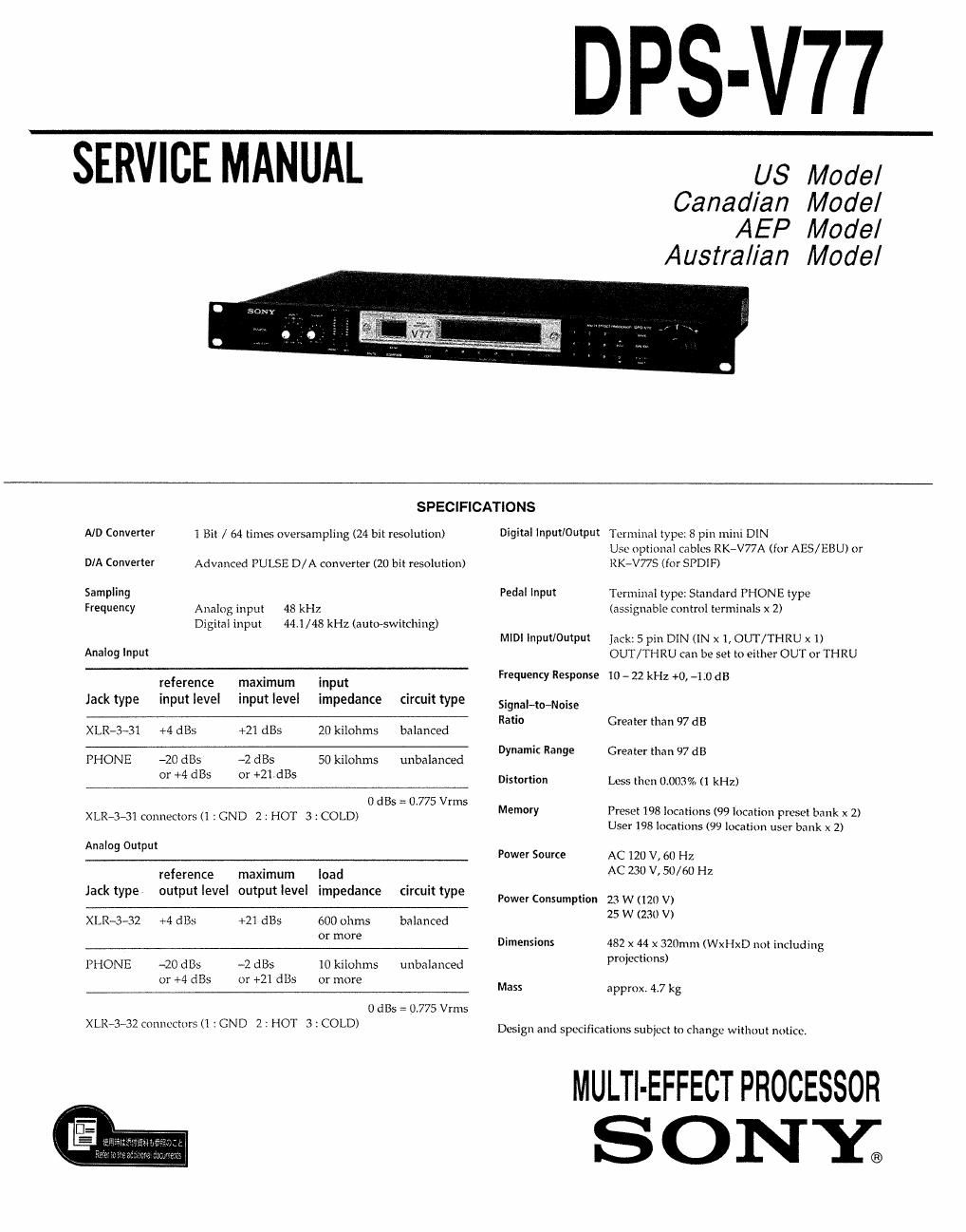
DPS-V77
SERVICE MANUAL
US Model
Canadian Model
AEP Model
Australian Model
SPECIFICATIONS
A/D Converter 1 Bit / 54 times oversampling (24 bit resolution) Digital Input/Output TerminaI type: 8 pin mini DIN
Use optional cables RK-V77A (for AES/EBU) or
D/A Converter Advanced PULSE D/A converter (20 bit resolution) RK-V77S (for SPDlF)
Sampling Pedal input Terminal type: Standard PHONE type
Frequency Analog input 48 kHz (assignable control terminals x 2)
Digital input 441/48 kHz (auto-switching)
Anang input
reference maximum input
Jack type input level input level impedance circuittype
XLR-3~31 +4 st +21 61135 20 kilohms balanced
PHONE -20 st ~2 (His 50 kilohrns unbalanced
or +4 st or +21st
O 6185 = 0,775 Vrms
XLR»3-31 connectors (l : GND 2 1 HOT 3 :COLD)
Analog Output
reference maximum load
Jack type output level output level impedance circuittype
XLRv3e32 +4 st +21 (21135 600 ohms balanced
or more
PHONE -20 L135 -2 L185 10 kilohms unbalanced
or +4 st or +21 (1135 or more
0 st = 0.775 Vrms
XLR~3A32 connectors (1 :GND 2 : HOT 3 : COLD)
MIDI Input/0MP jack: 5 pin DIN (IN X 1, OUT/THRU X I)
OUT/THRU can be set to either OUT or THRU
Frequency Response 10 _ 22 kHz +0, -1.0 dB
Signal-to-Noise
Ratio Greater than 97 dB
Dynamic Range Greater than 97 dB
Distortion Less then (lt0(l3% (1 kHz)
Memory Preset 198 locations (99 location prusot bank x 2)
User I98 locations (99 location user bank x 2)
Power Source AC 120 V, 60 H7.
AC 230 V, 50/60 Hz
Power Consumption 23 W (120 V)
25 W (230 V)
Dimensions 482 x 44 x 320mm (leIxD not including
projections)
Mass approx. 4.7 kg
Design and specifications subycct to change without notice.
MULTI-EFFECT PROCESSOR
SONY;
Page 2
TABLE OF CONTENTS
Section Title page
1, GENERAL ............................................................ 3
2. TEST MODE .............................. 17
3. CLOCK CONSTRUCTION .................................... 19
4. EXPLANATION OF Ic TERMINALS ....................... 20
5. DIAGRAMS
5.1. Block Diagram ............................................ 24
52 Printed Wiring Boards ~~ ~28
5-3. Schematic Diagram (1/2) - 33
5-4. Schematic Diagram (2/2) ~~~~~~~~~~~~~~~ ~38
6. EXPLODED VIEWS
6.1. Fro: Panel Section ....................................... 48
6-2. Chassis Section ~~~~~~~~~~~~~~~~~~~~~~~~~~~~~~~~~~~~~~~~~~~~~~ 49
7. ELECTRICAL PARTS LIST ~~~~~~~~~~~~~~~~~~~~~~~~~~~~~~~ SO
CAUTION
Danger of explosion if battery is incorrectly re
placed. Replace only with the same or equivalent
type recommended by the equipment manufacturer.
Discard used batteries according to manufacturers
instructions.
ADVARSEL I
Lithiumbatterikasplosionsfare ved fejlagtig handtering.
Udskiftning m5 kun ske med batteri
at samme fabrikat 03 type
Lever det brugte batteri tilbage til leverandcren.
ADVARSEL
Eksplosjonsfare ved feilaktig skifte av batteri.
Benytt samme batteritype eller en tilsvarende
type anbefalt av apparatfabrikanten.
Brukte batterier kasseres i henhold til fabrikantens
instruksjoner.
VARNING
Explosionsfara vid felaktigt batteribyte. Anvand samma
batterityp eller en likvardig typ som rekommenderas av
apparattillverkarenr Kassera anvant batteri enligt gallande
foreskrifter.
VAROITUS
Paristo voi rajahtaa, jos se on virheellisesti asennettur Vaihda
paristo ainoastaan Iaitevalmistaian suosittelemaan tyyppiin,
Havita kaytetty paristo valmistajan ohjeiden mukaisesti.
SAFETY CHECK~OUT (US Model)
After correcting the original service problem
perform the following safety check before releasing
the set to the customer:
Check the antenna terminals, metal trim, metallized
knobs, screws, and all other exposed metal parts for
AC leakage. Check leakage as described below.
LEAKAGE TEST
The AC leakage from any exposed metal part to
earth ground and from all exposed metal parts to any
exposed metal part having a return to chassis. must
not exceed 0.5 mA (500 microampers). Leakage
current can be measured by any one of three
methods.
I. A commercial leakage tester, such as the
Simpson 229 or RCA WT-S40A. Follow the
manufacturers' instructions to use these instru-
ments.
to
A battery-operated AC milliammeter. The Data
Precrsron 245 digital multimeter is suitable for
this job.
3. Measuring the voltage drop across a resistor by
means of :i VOM or battery-operated AC volt«
meter. The limit" indication is 07SV. so
analog meters must have an accurate low-
voltage scale. The Simpson 250 and Sunwa
SH-63Trd are examples of a passive VOM that
is suitable. NEarIy all battery operated digital
multimeters that have 2 2V AC range are
suitable. (See Fig. A)
To Exposed Metal
Pam on 52!
AC
0.15M 1.5m voltmeter
to. 75 1/)
5E Earth Ground
Fig. A. Using an AC voltmeter to check AC leakage.
SAFETY-RELATED COMPONENT WARNING
COMPONENTS IDENTIFIED BY MARK & OR DOTTED
LINE WITH MARK A ON THE SCHEMATIC DIAGRAMS
AND IN THE PARTS LIST ARE CRITICAL TO SAFE
OPERATION. REPLACE THESE COMPONENTS WITH
SONY PARTS WHOSE PART NUMBERS APPEAR AS
SHOWN IN THIS MANUAL OR IN SUPPLEMENTS PUB-
LISHED BY SONYT
ATTENTION AU COMPOSANT AYANT RAPPORT
A LA SECURITE!
LES COMPOSANTS IDENTIFIES PAR UNE MAROUE &
sun LES DIAGRAMMES SCHEMATIQUES ET LA LISTE
DES PIECES SONT CRITIQUES POUR LA sEcunITE
DE FONCTIONNEMENT. NE REMPLACER ces coM-
POSANTS QUE PAR DES PIECES SONY DONT LEs
NUMEROS SONT DONNES DANS ce MANUEL 0U
DANS LES SUPPLEMENTS PUBLIES PAR SONY.