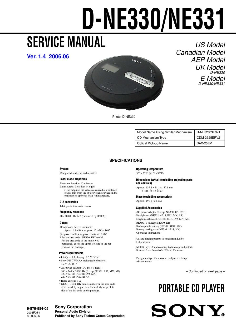
Sony d ne 330 service manual
This is the 42 pages manual for sony d ne 330 service manual.
Read or download the pdf for free. If you want to contribute, please upload pdfs to audioservicemanuals.wetransfer.com.
Extracted text from sony d ne 330 service manual (Ocr-read)
Page 1
2 D-NE330/NE331 SAFETY-RELATED COMPONENT WARNING!! COMPONENTS IDENTIFIED BY MARK 0 OR DOTTED LINE WITH MARK 0 ON THE SCHEMATIC DIAGRAMS AND IN THE PARTS LIST ARE CRITICAL TO SAFE OPERATION. REPLACE THESE COMPONENTS WITH SONY PARTS WHOSE PA RT NUMBERS APPEAR AS SHOWN IN THIS MANUAL OR IN SUPPLEMENTS PUBLISHED BY SONY. Notes on chip component replacement - Never reuse a disconnected chip component. - Notice that the minus side of a tantalum capacitor may be damaged by heat. Flexible Circuit Board Repairing - Keep the temperature of the soldering iron around 270 ˚C during repairing. - Do not touch the soldering iron on the same conductor of the circuit board (within 3 times). - Be careful not to apply force on the conductor when soldering or unsoldering. CAUTION Use of controls or adjustments or performance of procedures other than those specified herein may result in hazardous radiation e xposure. . O T E S O N T H E ! # P O W E R A D A P T O R s $ I S C O N N E C T A L L P O W E R S O U R C E S W H E N T H E P L A Y E R I S N O T T O B E U S E D F O R A L O N G T I M E s 5 S E O N L Y T H E ! # P O W E R A D A P T O R S U P P L I E D ) F Y O U R P L A Y E R I S N O T S U P P L I E D W I T H A N ! # P O W E R A D A P T O R U S E A N ! # % ( ' ! # P O W E R A D A P T O R $ O N O T U S E A N Y O T H E R ! # P O W E R A D A P T O R ) T M A Y C A U S E A M A L F U N C T I O N . O T A V A I L A B L E I N ! U S T R A L I A A N D S O M E O T H E R R E G I O N S ! S K Y O U R D E A L E R F O R D E T A I L E D I N F O R M A T I O N 0 O L A R I T Y O F T H E P L U G s $ O N O T T O U C H T H E ! # P O W E R A D A P T O R W I T H W E T H A N D S s # O N N E C T T H E ! # P O W E R A D A P T O R T O A N E A S I L Y A C C E S S I B L E ! # O U T L E T 3 H O U L D Y O U N O T I C E A N A B N O R M A L I T Y I N T H E ! # P O W E R A D A P T O R D I S C O N N E C T I T F R O M T H E ! # O U T L E T I M M E D I A T E L Y Battery life 1) When using a Sony alkaline battery LR6 (SG) (produced in Japan) G-PROTECTION 1 2 Audio CD 22 20 A TRAC CD 2) 41 41 MP3 CD 3) 31 31 When using one NH-7WMAA rechargeable battery (charged for about 5 hours 4) 5)) G-PROTECTION 1 2 Audio CD 10 9 A TRAC CD 2) 17 15 MP3 CD 3) 12 11 1) Measured value using the JEITA (Japan - Abbreviation E18 : 100 – 240 V AC area in E model 1E18 : Singapore, Malaysia, Vietnam and Indian models AR : Argentina model CND : Canadian model E92 : Panama and Venezuelan models 4E18 : Chilean and Peruvian models FR : France model HK : Hong Kong model MX : Mexican modelElectronics and Information Technology Industries Association) Playing time shown is approximate hours, when you use the player on a flat and stable surface and POWER SAVE is set to ON This value varies depending on how the player is used. 2) Recorded at 48 kbps 3) Recorded at 128 kbps 4) Charging time varies depending on how the rechargeable battery is used. 5) NE331: 1E18, HK models only Ve r. 1.3 ATTENTION AU COMPOSANT AYANT RAPPORT À LA SÉCURITÉ! LES COMPOSANTS IDENTIFIÉS PAR UNE MARQUE 0 SUR LES DIAGRAMMES SCHÉMATIQUES ET LA LISTE DES PIÈCES SONT CRITIQUES POUR LA SÉCURITÉ DE FONCTIONNEMENT. NE REMPLACER CES COM- POSANTS Q UE PAR DES PIÈCES SONY DONT LES NUMÉROS SONT DONNÉS DANS CE MANUEL OU DANS LES SUPPLÉMENTS PUBLIÉS PAR SONY.
Page 2
3 D-NE330/NE331 TABLE OF CONTENTS 1. SERVICING NOTES ............................................... 4 2. GENERAL ................................................................... 5 3. DISASSEMBLY 3-1. Disassembly Flow ........................................................... 6 3-2. Cabinet Lower Sub Assy, Upper Lid Sub Assy ............... 6 3-3. MAIN Board, Optical Pick-Up Assy (CDM-3325ERV2) .......................................................... 7 3-4. SWITCH Board ............................................................... 7 4. DIAGRAMS 4-1. Schematic Diagram – MAIN Board (1/3) – .................... 9 4-2. Schematic Diagram – MAIN Board (2/3) – .................... 10 4-3. Schematic Diagram – MAIN Board (3/3) – .................... 11 4-4. Printed Wiring Board – MAIN Board (Component Side) – .............................. 12 4-5. Printed Wiring Board – MAIN Board (Conductor Side) – ................................. 13 4-6. Printed Wiring Board – SWITCH Board – ..................... 14 4-7. Schematic Diagram – SWITCH Board – ........................ 15 5. EXPLODED VIEWS 5-1. Upper Lid Section ........................................................... 22 5-2. Cabinet Lower Section .................................................... 23 5-3. Optical Pick-Up Section (CDM-3325ERV2) .................. 24 6. ELECTRICAL PARTS LIST ................................ 25