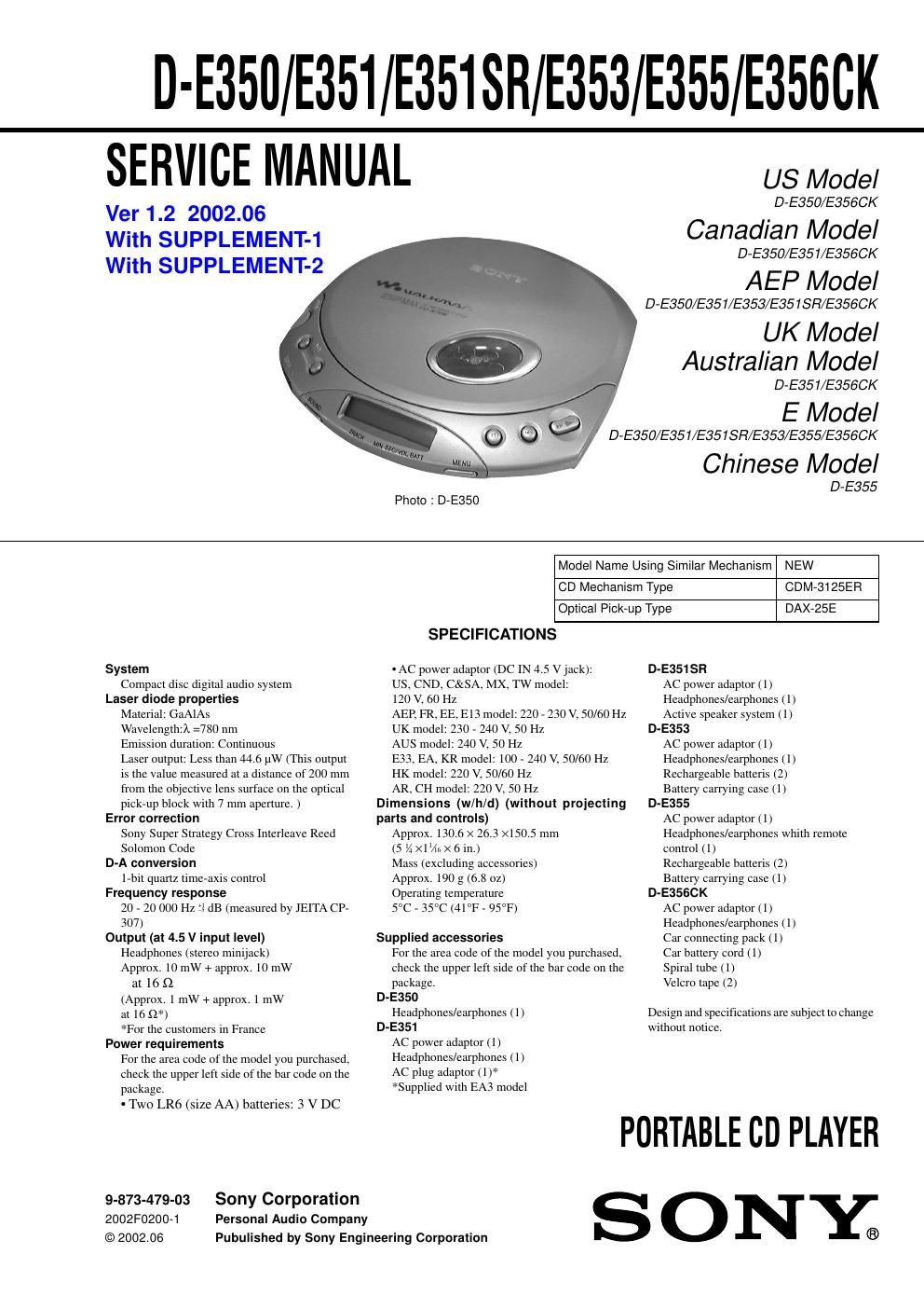
Sony d e 356 ck service manual
This is the 46 pages manual for sony d e 356 ck service manual.
Read or download the pdf for free. If you want to contribute, please upload pdfs to audioservicemanuals.wetransfer.com.
Extracted text from sony d e 356 ck service manual (Ocr-read)
Page 1
D-E35II E351 E351SR E353 E355 E3550K
SERVICE MANUAL
Ver 1.2 2002.06
With SUPPLEMENT-1
With SUPPLEMENT-2
US Model
D-E350/E3560K
Canadian Model
D-E350/E351/E3560K
AEP Model
D-E350/E351/E353/E351SFi/E356CK
UK Model
Australian Model
D-E351/E3560K
E Model
D-E350/E351/E351SR/E353/E355/E3560K
Chinese Model
System
Compact disc digital audio system
Laser diode properties
Material: GaAlAs
Wavelength?» =780 nm
Emission duration: Continuous
Laser output: Less than 44.6 uW (This output
is the value measured at a distance of 200 mm
from the objective lens surface on the optical
pick-up block with 7 mm aperture. )
Error correction
Sony Super Strategy Cross Interleave Reed
Solomon Code
D-A conversion
l-bit quartz time»axis control
Frequency response
20 - 20 000 Hz 1; dB (measured by JEITA CP-
307)
Output (at 4.5 V input level)
Headphones (stereo minijack)
Approx. 10 mW + approx. 10 mW
at 16 £2
(Approx. 1 mW+ approx. 1 mW
at 16 52*)
*For the customers in France
Power requirements
For the area code of the model you purchased,
check the upper left side of the bar code on the
package.
- Two LR6 (size AA) batteries: 3 V DC
9-873-479-03 Sony Corporation
2002F0200-1 Personal Audio Company
© 2002.06
D-E355
Photo : D-E350
Model Name Using Similar Mechanism NEW
CD Mechanism Type CUM-3125ER
Optical Pick-up Type BAX-25E
SPECIFICATIONS
- AC power adaptor (DC IN 4.5 Vjack):
US, CND, C&SA, MX, TW model:
120 V, 60 Hz
AEP, FR, EE, E13 model: 220 - 230V, 50/60 Hz
UK model: 230 - 240 V, 50 Hz
AUS model: 240 V, 50 Hz
E33, EA, KR model: 100 - 240 V, 50/60 Hz
HK model: 220 V, 50/60 Hz
AR, CH model: 220 V, 50 Hz
Dimensions (w/h/d) (without projecting
parts and controls)
Approx. 130.6 x 26.3 X1505 mm
(5 % >
Mass (excluding accessories)
Approx. 190 g (6.8 oz)
Operating temperature
5°C - 35C (41F - 95°F)
Supplied accessories
D-E351 SR
Design and specifications are subject to change
PORTABLE CD PLAYER
Pubulished by Sony Engineering Corporation
ONE
For the area code of the model you purchased,
check the upper left side of the bar code on the
package.
D-E350
Headphones/earphones (l)
D-E351
AC power adaptor (l)
Headphones/earphones (1)
AC plug adaptor (1)*
*Supplied with EA3 model
AC power adaptor (l)
Headphones/earphones (1)
Active speaker system (1)
D-E353
AC power adaptor (l)
Headphones/earphones (l)
Rechargeable batteris (2)
Battery carrying case (1)
D-E355
AC power adaptor (l)
Headphones/earphones whith remote
control (1)
Rechargeable batteris (2)
Battery carrying case (1)
D-E356CK
AC power adaptor (l)
Headphones/earphones (1)
Car connecting pack (1)
Car battery cord (1)
Spiral tube (1)
Velcro tape (2)
without notice.
Page 2
D-E350/E351/E351SR/E353/E355/E356CK
. Abbreviation
AUS : Australian CND : Canadian
FR : French HK : Hong Kong
AR : Argentina EA : audi Arabia
CH : Chinese EE : East European
TW : Taiwan MX : Mexico
KR : Korean
C&SA : Central and South America
E13 : AC220-230V area model
E33 : AC100-240V area model
DANGER
Invisible laser radiation when open and interlock failed or defeated.
Avoid direct exposure to beam.
CAUTION
Use of controls or adjustments or performance of procedures other
than those specified herein may result in hazardous radiation
exposure.
Laser component in this product is capable of emitting
radiation exceeding the limit for Cl' s l.
This Compact Disc player is
classified as a CLASS 1 LASER
product.
The CLASS I LASER
PRODUCT label is located on
the rear exterior.
CLASS 1 LASER PRODUCT
LUOKAN 1 LASERLAITE
KLASS 1 LASERAPPARAT
Flexible Circuit Board Repairing
. Keep the temperature of the soldering iron around 270°C during
repairing.
' Do not touch the soldering iron on the same conductor of the
circuit board (within 3 times).
' Be careful not to apply force on the conductor when soldering or
unsoldering.
Notes on chip component replacement
' Never reuse a disconnected chip component.
- Notice that the minus side of a tantalum capacitor may be damA
aged by heat.
TABLE OF CONTENTS
Specifications ............................................................................ l
1. SERVICING NOTES ................................................... 3
2. GENERAL
Locating the Controls ......................................................... 3
3. DISASSEMBLY
3»l. Cabinet (Lower), MD ASSY .
372. Main Board .........................
373. Motor ASSY, Turn Table (Spindle) (M9OI)
374. Motor ASSY (Spindle) (M902),
Optical Pickiup (DAX-ZSE) ...................................... 5
4. ELECTRICAL ADJUSTMENS ............................... 6
5. DIAGRAMS
5»l. Explanation of IC Terminals
572. Block Diagram ......
53. Printed Wiring Board
5-4. Schematic Diagram iMAIN SECTION (1/3)7
55. Schematic Diagram iMAIN SECTION (2/3)7
56. Schematic Diagram iMAIN SECTION (3/3}
6. EXPLODED VIEWS
6*]. Cabinet Section .....
672. Optical pickiup Section (CDM-3125ER)
7. ELECTRICAL PARTS LIST ................................... 18
SAFETY-RELATED COMPONENT WARNING!!
COMPONENTS IDENTIFIED BY MARK A 0R DOTTED LINE
WITH MARK A ON THE SCHEMATIC DIAGRAMS AND IN THE
PARTS LIST ARE CRITICALTO SAFE OPERATION.
REPLACE THESE COMPONENTS WITH SONY PARTS WHOSE
PART NUMBERS APPEAR AS SHOWN IN THIS MANUAL OR IN
SUPPLEMENTS PUBLISHED BY SONY.
ATTENTION AU COMPOSANT AYANT RAPPORT
A LA SECURITE!
LES COMPOSANTS IDENTIFIES PAR UNE MAROUE A SUR LES
DIAGRAMMES SCHEMATIQUES ET LA LISTE DES PIECES
SONT CRITIQUES POUR LA SECURITE DE FONCTIONNEMENT.
NE REMPLACER CES COMPOSANTS QUE PAR DES PIECES
SONY DONT LES NUMEROS SONT DONNES DANS CE MANUEL
0U DANS LES SUPPLEMENTS PUBLIES PAR SONY.