Sony cmt a 70 service manual

This is the 74 pages manual for sony cmt a 70 service manual.
Read or download the pdf for free. If you want to contribute, please upload pdfs to audioservicemanuals.wetransfer.com.

Page: 1 / 74
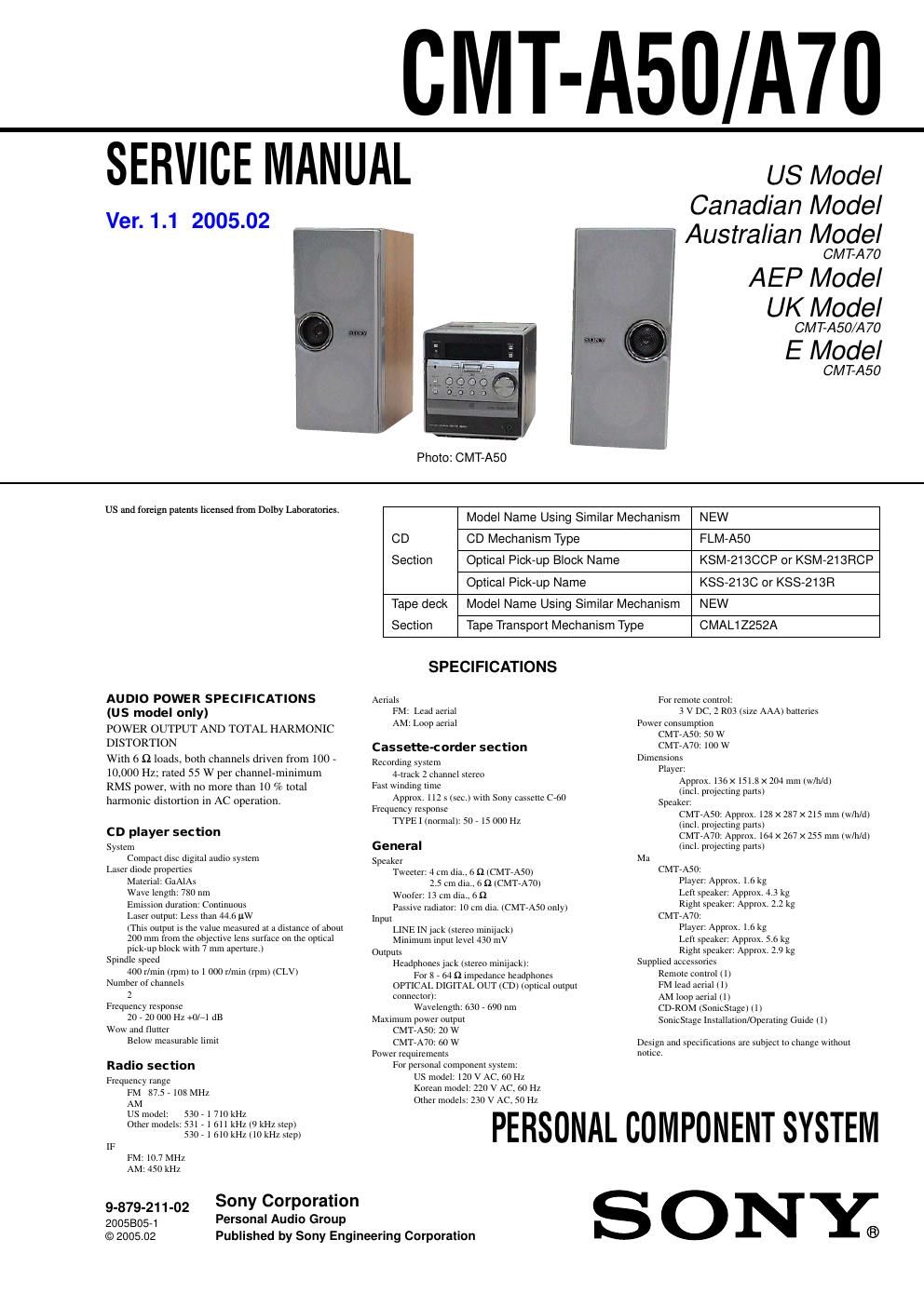
sony cmt a 70 service manual

Extracted text from sony cmt a 70 service manual (Ocr-read)


Page 2

3 CMT-A50/A70 TABLE OF CONTENTS 1. SERVICING NOTES ............................................... 4 2. GENERAL ................................................................... 6 3. DISASSEMBLY 3-1. Disassembly Flow ........................................................... 9 3-2. Cabinet Rear .................................................................... 10 3-3. CD Door ........................................................................\ .. 10 3-4. CD Mechanism Deck (FLM-A50) .................................. 11 3-5. SUB Board ...................................................................... 11 3-6. Top Case Assy ................................................................. 12 3-7. MAIN Board .................................................................... 12 3-8. CD Board ........................................................................\ . 13 3-9. Tray ........................................................................\ .......... 13 3-10. Optical Pick-up Block (KSM-213CCP or KSM-213RCP) .................................. 14 3-11. Optical Pick-up (KSS-213C) ........................................... 14 3-12. Optical Pick-up (KSS-213R) ........................................... 15 3-13. Tape Mechanism Deck (CMAL1Z252A) ........................ 15 4. TEST MODE .............................................................. 16 5. ELECTRICAL ADJUSTMENTS Deck Section .................................................................... 18 CD Section ...................................................................... 19 6. DIAGRAMS 6-1. Block Diagram – SERVO Section – ............................... 20 6-2. Block Diagram – MAIN Section – ................................. 21 6-3. Block Diagram – PANEL, POWER SUPPLY Section – .......................... 22 6-4. Printed Wiring Board – CD Board – .............................. 24 6-5. Schematic Diagram – CD Board – ................................. 25 6-6. Printed Wiring Board – MAIN Board (Component Side) – ............................... 26 6-7. Printed Wiring Board – MAIN Board (Conductor Side) – ................................. 27 6-8. Schematic Diagram – MAIN Board (1/2) – ................... 28 6-9. Schematic Diagram – MAIN Board (2/2) – ................... 29 6-10. Printed Wiring Board – SUB Board – ............................ 30 6-11. Schematic Diagram – SUB Board – ............................... 31 6-12. Printed Wiring Boards – PANEL, MOTOR Section – ... 32 6-13. Schematic Diagram – PANEL, MOTOR Section – ........ 33 6-14. Printed Wiring Boards – AMP, POWER SUPPLY Section (CMT-A50 only) – .. 34 6-15. Schematic Diagram – AMP, POWER SUPPLY Section (CMT-A50 only) – .. 35 6-16. Printed Wiring Boards – AMP Section (CMT-A70 only) – ................................. 36 6-17. Schematic Diagram – AMP Section (CMT-A70 only) – ................................. 37 6-18. Printed Wiring Board – POWER SUPPLY Section (CMT-A70 only) – ............ 38 6-19. Schematic Diagram – POWER SUPPLY Section (CMT-A70 only) – ............ 39 7. EXPLODED VIEWS 7-1. Overall Section ................................................................ 50 7-2. Front Panel Section ......................................................... 51 7-3. Top Case Section ............................................................. 52 7-4. CD Mechanism Deck Section (FLM-A50) ..................... 53 7-5. Optical Pick-up Section (KSM-213CCP) ........................ 54 7-6. Optical Pick-up Section (KSM-213RCP) ........................ 55 7-7. Speaker (Left) Section (A50) .......................................... 56 7-8. Speaker (Right) Section (A50) ........................................ 57 7-9. Speaker (Left) Section (A70) .......................................... 58 7-10. Speaker (Right) Section (A70) ........................................ 59 8. ELECTRICAL PARTS LIST ................................ 60