Sony cfs w 504 service manual

This is the 22 pages manual for sony cfs w 504 service manual.
Read or download the pdf for free. If you want to contribute, please upload pdfs to audioservicemanuals.wetransfer.com.

Page: 1 / 22
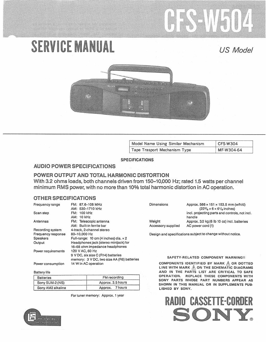
sony cfs w 504 service manual

Extracted text from sony cfs w 504 service manual (Ocr-read)


Page 1

SERVICE MANUAL

US Model

Model Name Using Similar Mechanism CFS-W304
Tape Trasport Mechanism Type MF-W304-64
SPECIFICATIONS

AUDIO POWER SPECIFICATIONS

POWER OUTPUT AND TOTAL HARMONIC DISTORTION
With 3.2 ohms loads, both channels driven from 150-10,000 Hz; rated 1.5 watts per channel
minimum RMS power, with no more than 10% total harmonic distortion in AC operation.

OTHER SPECIFICATIONS
Frequency range FM: 87.6-108 MHz
AM: 530-1 710 kHz
Scan step FM: 100 kHz
AM: 10 kHz
Antennas FM: Telescopic antenna

AM: Built-in ferrite bar
Recording system 4-track, 2-channel stereo
Frequency response 80-1 0.000 H2
Speakers Full-range: 10 cm (4 inches) dia. x 2
Output Headphonesjack (stereo minijack) for

16-68 ohm impedance headphones
Power requirements 120 V AC. 60 Hz

9 V DC, six size 0 (R14) batteries

memory: 3 V DC, two size AA (R6) batteries
Power consumption 14 W in AC operation

Battery life

Batteries

FM recording

Sony SUM-2 (NS)

Approx. 3.5 hours

Sony AM2 alkaline

Approx. 7 hours

For tuner memory: Approx. 1 year

Dimensions Approx. 566 x 151 x 153.5 mm (w/hld)
(223/a x s x sue inches)
incl. projecting parts and controls, not incl.
handle
Weight Approx. 3.0 kg (6 lb 10 oz) incl. batteries
Accessory supplied AC power cord (1)

Design and specifications subject to change without notice.

SAFETY-RELATED COMPONENT WARNING

COMPONENTS IDENTIFIED BY MARK A OR DOTTED
LINE WITH MARK A ON THE SCHEMATIC DIAGRAMS
AND IN THE PARTS LIST ARE CRITICAL TO SAFE
OPERATION. REPLACE THESE COMPONENTS WITH
SONY PARTS WHOSE PART NUMBERS APPEAR AS
SHOWN IN THIS MANUAL OR IN SUPPLEMENTS PUB-
LISHED BY SONY.

RADlll CASSETTE-BORDER
S 0 NYC.

Page 2

CFS-W504

SAFETY CH ECK-OUT 3. Measuring the voltage drop across a resistor by
means of a VOM or battery-operated AC volt-
meter. The limit indication is 0.75 V, so
analog meters must have an accurate low
voltage scale. The Simpson 250 and Sanwa
SH-63Trd are examples of a passive VOM that
is suitable. Nearly all battery operated digital
multimeters that have 3 2V AC range are
suitable. (See Fig. A)

After correcting the original service problem,
perform the following safety check before releasing
the set to the customer:

Check the antenna terminals, metal trim, metallized
knobs, screws, and all other exposed metal parts for
AC leakage. Check leakage as described below.

LEAKAGE TEST

The AC leakage from any exposed metal part to ;:r§?:§: Mam

earth ground and from all exposed metal parts to any
exposed metal part having a return to chassis, must
not exceed 0.5 mA (500 microampers). Leakage
current can be measured by any one of three

methods. 0.15uF §I.5kfl / fiastmerer
l. A commercial leakage tester, such as the > {0.75Vl
Simpson 229 or RCA WT540A. Follow the
manufacturers instructions to use these instru-
ments. -:-

.- Earth Ground
2. A battery-operated AC milliammeter. The Data
Precision 245 digital multimeter is suitable for

Fig. A. Using an AC voltmeter to check AC leakage.

this job.

SECTION 1
DISASSEMBLY

Note : Follow the disassembly procedure in the numerical order given.
REMOVAL OF CASSETTE HOLDER

Remove the cassette holder
shown by arrow Q