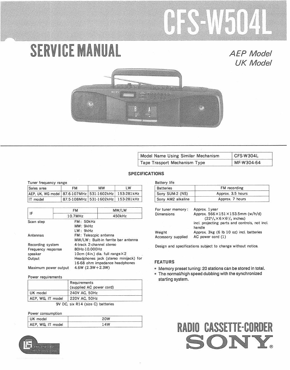
Sony cfs w 504 l service manual
This is the 25 pages manual for sony cfs w 504 l service manual.
Read or download the pdf for free. If you want to contribute, please upload pdfs to audioservicemanuals.wetransfer.com.
Extracted text from sony cfs w 504 l service manual (Ocr-read)
Page 1
SERVlCE MANUAL
AEP Model
UK Model
Model Name Using Similar Mechanism CFS-W304L
Tape Trasport Mechanism Type MF-W304-64
SPECIFICATIONS
Tuner frequency range Battery life
Sales area FM MW LW Batteries FM recording
AEP, UK, WG model 87.6-107MHZ 531-1602kHz 153-281 kHz Sony SUM»2 (NS) Approx 3.5 hours
IT model 87.5»108MH2 531-1602kHz 153-281 kHz Sony AM2 alkaline Approx, 7 hours
lF FM MW/LW For tuner memory: Approx. lyear
Dimensions Approx. 566x 151 X 153.5mm (w/h/d)
10,7Ml-Iz 450kHZ (223/3X6X61/3 inches)
Scan Step FM' 50kHz incl. projecting parts and controls, not incl
MW: 9kHz handle
LW 9 _ Weight Approx 3kg (6 lb 10 oz) incle batteries
Antennas FM: Telescpic antenna AC power cord (1)
Recording system
Frequency response
spea ker
Output
Maximum power output
Power requirements
MW/LW: Built-in ferrite bar antenna
4-track 2-channel stereo
80Hz»10.000HZ
10cm (4int) diae full range><2 .
Headphones jack (stereo minijack) for
16-68 ohm impedance headphones
4.6W (2.3W+2.3W)
Accessory supplied
Design and specifications subject to change without notice.
FEATU RS
- Memory preset tuning: 20 stations can be stored in total.
- The normal/high speed dubbing with the synchronized
starting system.
Requirements
(supplied AC power cord)
UK model
240V AC, 50Hz
AEP, WG, IT model
220V AC, 50HZ
9V DC,
Power consumption
six R14 (size C) batteries
UK model
20W
AEP, WG, IT model
14W
RADIO CASSETTE-BORDER
ONE
Page 2
CF S-W504L
MODEL IDENTIFICATION
-Model Number Label-
AEP, WG, IT model: Carved on rear cabinet
UK model: Model number label
WG : West Germany model
I? : Italian model
SONY» MODEL N0. CFS-W504L
RADIO CASSETTE-CORDER
E
Except UK model: AC: 220V~50Hz 14W
{UK model : AC: 240V~50Hz 20W
fl UK model: 336343401
SA FETY-R ELATED COMPONENT WAR N ING!!
COMPONENTS IDENTIFIED BY MARK A OR DOTTED
LINE WITH MARK A ON THE SCHEMATIC DIAGRAMS
AND IN THE PARTS LIST ARE CRITICAL T0 SAFE
OPERATION. REPLACE THESE COMPONENTS WITH
SONY PARTS WHOSE PART NUMBERS APPEAR AS
SHOWN IN THIS MANUAL OR IN SUPPLEMENTS PUB-
LISHED BY SONV.
Note : Follow the disassembly procedure in the numerical order given.
REMOVAL OF CASSETTE HOLDER
SECTION 1
DISASSEMBLY
Remove {he casseIte holder
shown by arrow 0