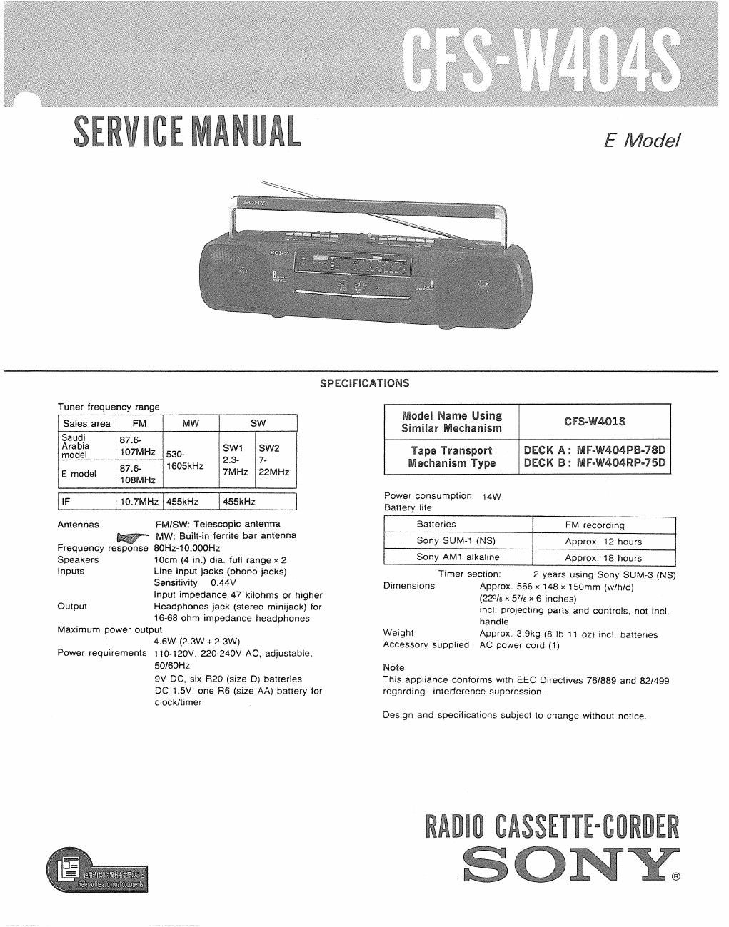
Sony cfs w 404 s service manual
This is the 28 pages manual for sony cfs w 404 s service manual.
Read or download the pdf for free. If you want to contribute, please upload pdfs to audioservicemanuals.wetransfer.com.
Extracted text from sony cfs w 404 s service manual (Ocr-read)
Page 1
E Model
SPECIFICATIONS
Tuner frequency range
Sales area FM MW SW
gaugi 87.5
ra ia
model 107MHz 530- SW1 SW2
6 1605kHz 23' 7'
87 7MHz 22MHZ
E model 108MHz
IF 110.7MH21455kHz j455kHz
Antennas FM/SW: Telescopic antenna
MW: Built-in ferrite bar antenna
Frequency response 80Hz-10,000H2
Speakers
Inputs
Output
10cm (4 in.) dia. full range x 2
Line input jacks (phono jacks)
Sensitivity 0.44v
Input impedance 47 kilohrns or higher
Headphones jack (stereo minijack) for
16-68 ohm impedance headphones
Maximum power output
Power requirements
4.6W (2.3w + 2,3wi
110»120V, 220-240V AC. adjustable.
50/60Hz
9V DC. six R20 (sxze D) batteries
DC 1.5V. one R6 (size AA) battery for
clock/timer
Model Name Using
Similar Mechanism
Tape Transport DECK A: MF-W404PB-78D
Mechanism Type DECK B: MF-W404RP-75D
C FS-W40 1 S
Power CONSUmDIlOfi 14W
Battery lite
Batteries FM recording
Sony SUM-1 (NS) Approx. 12 hours
Sony AM1 alkaline Approx. 18 hours
Timer section: 2 years using Sony SUM-3 (NS)
Dimen5ions Approx. 566 x 148 x 150mm (w/h/d)
(223/3 x 57/5 x 6 inches)
incl, projecting parts and controls, not incl.
handle
Weight Approx, 3.9kg (8 lb 11 oz) incl. batteries
Accessory supplied AC power cord (1)
Note
This appliance conforms with EEC Directives 76/889 and 82/499
regarding interference suppression
Beetgn and specifications subject to change without notice.
RADlll CASSETTE-BORDER
ONY;
Page 2
CFS-W404S
FEATU R ES
0 The autdreverse function enables playback on both
sides of a cassette without having to turn over the
cassette.
0 The graphic equalizer controls allow you to get the
desired tone quality.
0 The AMS function starts from the beginning of the
desired selectioni
- The normal/high speed dubbing with the synchronized
starting system.
0 Built-in digital clock timer.
SERVICING NOTE
ORepairing printed resistor
Cut both sides of the resistor and solder the carbon resistor
having same value in place of printed one of the conductor
side.
1/ 4W carbon resistor is supplied for the replacing part of the
printed resistor.
0 Note for tape operation buttons
When replacing tape operation buttons, cut them off and
attach new parts with locking compound. (Refer to page 7.)
SAFETY-RELATED COMPONENT WARNING
COMPONENTS IDENTIFIED BY MARK A OR DOTTED
LINE WITH MARK A
ON THE SCHEMATIC DIAGRAMS
AND IN THE PARTS LIST ARE CRITICAL TO SAFE
OPERATION. REPLACE THESE COMPONENTS WITH
SONY PARTS WHOSE PART NUMBERS APPEAR AS
SHOWN IN THIS MANUAL OR IN SUPPLEMENTS PUB-
LISHED BY SONY.
izi