Sony cfs w 365 s service manual

This is the 24 pages manual for sony cfs w 365 s service manual.
Read or download the pdf for free. If you want to contribute, please upload pdfs to audioservicemanuals.wetransfer.com.

Page: 1 / 24
sony cfs w 365 s service manual

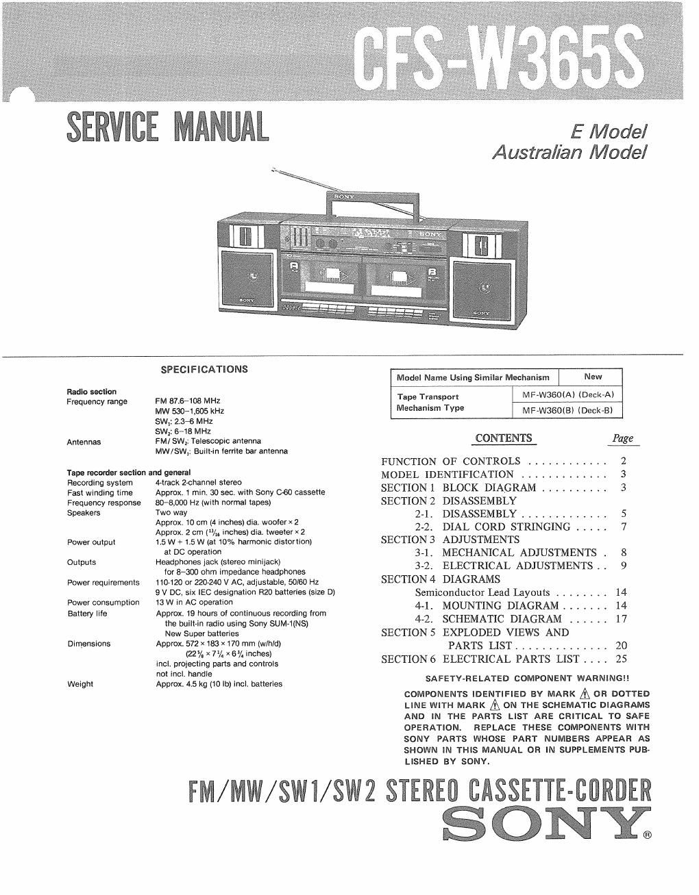
Extracted text from sony cfs w 365 s service manual (Ocr-read)


Page 1

E Model
Australian Model

Radio section
Frequency range

Antennas

SPECIFICATIONS

FM 87,6»108 MHZ

MW 530-1505 kHz

SW,: 23-6 MHZ

SW2: 6*18 MHz

FM/ SW; Telescopic antenna
MW/SW,: Built-in ferrite bar antenna

Tape recorder section and general

Recording system
Fast winding time
Frequency response
Speakers

Power output
Outputs

Power requirements
Power consumption

Battery life

Dimensions

Weight

A-track 2-channel stereo
Approx. 1 min, 30 see. with Sony 060 cassette
80-8900 Hz (with normal tapes)
Two way
Approx. 10 cm (4 inches) dia. woofer x 2
Approx. 2 cm (/,. Inches) dia. tweeterx 2
1.5W + 1.5 W (at 10% harmonic distortion)
at DC operation
Headphones jack (stereo minijack)
tor 8-300 ohm impedance headphones
110-120 or 220-240 V AC, adjustable, 50/60 Hz
9 V DC, six IEC designation R20 batteries (size D)
13 w in AC operation
Approx, 19 hours oi continuous recording from
the built-in radio using Sony SUM-1INS)
New Super batteries
Approx 572 X 183 X 170 mm (w/hld)
(22% ><7/. x67. inches)
incl. projecting pans and controls
not incl. handle
Approx 45 kg (10 lb) incl. batteries

Model Name Using Similar Mechanism New

MF-W3GO(A) (Deck-A)
MF-WBGOIBI (Deck-BI

Tape Transport
Mechanism Type

CONTENTS Page
FUNCTION OF CONTROLS ............ 2
MODEL IDENTIFICATION ............. 3
SECTIONI BLOCK DIAGRAM .......... 3
SECTIONZ DISASSEMBLY
2~1. DISASSEMBLY . . . . . r . . 5
2-2. DIAL CORD STRINGING ..... 7

SECTION3 ADJUSTMENTS
3-1. MECHANICAL ADJUSTMENTS . 8
32. ELECTRICAL ADJUSTMENTS . . 9
SECTION4 DIAGRAMS

Semiconductor lead layouts ........ 14

4-1. MOUNTING DIAGRAM ....... 14

4-2. SCHEMATIC DIAGRAM ...... 17
SECTION 5 EXPLODED VIEWS AND

PARTS LIST .......... . 20

SECTION6 ELECTRICAL PARTS LIST . . . . 25

SAFETY-RELATED COMPONENT WARNINGII

COMPONENTS IDENTIFIED BY MARK A OR DOTTED
LINE WITH MARK A ON THE SCHEMATIC DIAGRAMS
AND IN THE PARTS LIST ARE CRITICAL TO SAFE
REPLACE THESE COMPONENTS WITH
SONY PARTS WHOSE PART NUMBERS APPEAR AS
SHOWN IN THIS MANUAL OR IN SUPPLEMENTS PUB-

OPERATION.

LISHED BY SONYI

FM/MW/SWI/SWZ SIEREII CASSETTE-CDRDER

SONY®