Sony cfs kw 75 s service manual

This is the 31 pages manual for sony cfs kw 75 s service manual.
Read or download the pdf for free. If you want to contribute, please upload pdfs to audioservicemanuals.wetransfer.com.

Page: 1 / 31
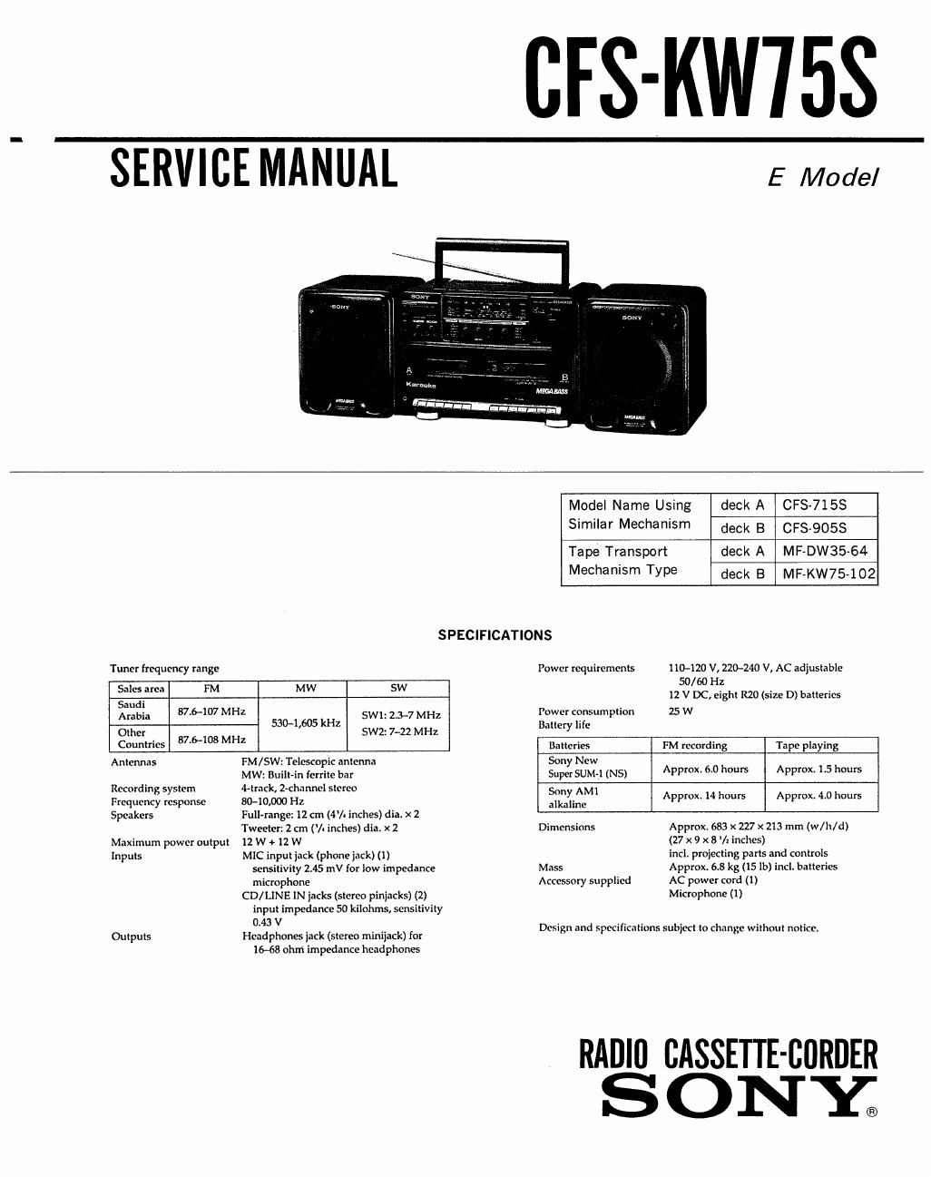
sony cfs kw 75 s service manual

Extracted text from sony cfs kw 75 s service manual (Ocr-read)


Page 1

SERVICE MANUAL

CFS-KWISS

Kurunka

Winn-Ian-m-mn!

E Model

Model Name Using deck A CFS-715S
Similar Mechanism deck B CFS-9058
Tape Transport deck A MF-DW35A64
Mechanism Type deck 8 MF-KW75-102

SPECIFICATIONS
Tuner frequency range Power requirements 110-120 V, 220-240 V, AC adjustable
50/60 Hz
swim FM MW SW i2 v DC, eight R20 (size D) batteries
Saudi
Arabia 37-6407 MHZ sw1: 23-7 MHz Power comumpfion 25 W
530-1le kHz Battery Ii {12
Other 87 6-108 MHz SW1 7-22 MHz
Countries ' Baileries FM recording Tape playing
Antennas FM / SW: Teleswpic anlcnna Sony New
MW: Built-in ferrite bar Super SUM-1 (NS) APP 50 0 APP><~ 5 IOWS
Recording system 4-Irnck, Z-chnnnei slcrco
qumy response $040,000 H1 $3.35 Approx. 14 hours Approx. 4.0 hours
Speakers Full-range: 12 cm (4% Inches) dia. x 2
Tweeter: 2 cm (/- inches) dia. x 2 Dimensions Approx. 683 x 227 X 213 mm (w/h/d)
Maximum power outpul 12 W <1 12 W (27 x 9 x 8 '/x inches)
inputs MIC input jack (phone jack) (1) incIi proiecling parks and controls
sensitivity 2.45 mV for low impedance Mass Approx. 6.8 kg (15 lb) incl. baneries
microphone Accessory supplied AC power cord (1)
CD/ LINE IN jacks (stereo pinjacks) (2) Microphone (1)
inpul impedance 50 kilohms, sensitivity
Outpuis Hgnzixones jack (stereo miniiack) for Design and specifications subject to change without notice.

16~68 ohm impedance headphones

RADIfl CASSETTE-BURDER
S 0 NY.

Page 2

MODEL IDENTIFICATION
-Model Number Labal-

SONYQ

MODEL N0. CFS-KW7SS

RADIO CASSETTE-CORDER
AC: 110-120/220-240V~50/60Hz 25W

W

E12, E23 model: 3909-67001
EA, UAE model : 3909-66901

OAbbreviations
E12 : A0220-240V Area model
E23: ACl IO-lZOV Area model
EA : Saudi Arabia model
UAE: United Arab Emirates model

SAFETV-RELATED COMPONENT WARNING

COMPONENTS IDENTIFIED BY MARK A 0R DOTTED
LINE WITH MARK A ON THE SCHEMATIC DIAGRAMS
AND IN THE PARTS LIST ARE CRITICAL TO SAFE
REPLACE THESE COMPONENTS WITH
SONY PARTS WHOSE PART NUMBERS APPEAR AS
SHOWN IN THIS MANUAL OR IN SUPPLEMENTS PUB-

OPERATION.

LISHED BY SONY.

TABLE OF CONTENTS


Section Title Page
1. GENERAL

1-1. Parts Identification ........................... 3
2. DISASSEMBLY

2-1. Cassette Lid ................................. 5

2-2. Rear Cabinet ................................. 5

23. Main board .................................... 6

2-4 Pointer Setting , ........................... 6
3. MECHANICAL ADJUSTMENTS .................. 7
4. ELECTRICAL ADJUSTMENTS

4-1, Tape Recorder Section ....................... 7

4-2. Radio Section .................................. 8
5. DIAGRAMS

5-1. Circuit Boards Location

5-2. Semiconductor Lead Layouts ..................

58. Printed Wiring Boards ........................ 11

5-4, Schematic Diagram-Main Section- .......... 15

5-5, Schematic Diagram-KARAOKE Section- 4 . . ,19

6. EXPLODED VIEWS

6-1, Rear Cabinet Section .i i
62. Front Cabinet Section ........................ 22
6-3. Mechanism Deck Section (1) .................. 24
6-4. Mechanism Deck Section (2) .................. 25
6-5. Mechanism Deck Section (3) .................. 26
6-6. Mechanism Deck Section (4) .................. 28
6-7. Speaker Section .............................. 29
7. ELECTRICAL PARTS LIST iiiiiiiiiiiiiiiiiiiiii 30