Sony cfs kw 250 s service manual

This is the 26 pages manual for sony cfs kw 250 s service manual.
Read or download the pdf for free. If you want to contribute, please upload pdfs to audioservicemanuals.wetransfer.com.

Page: 1 / 26
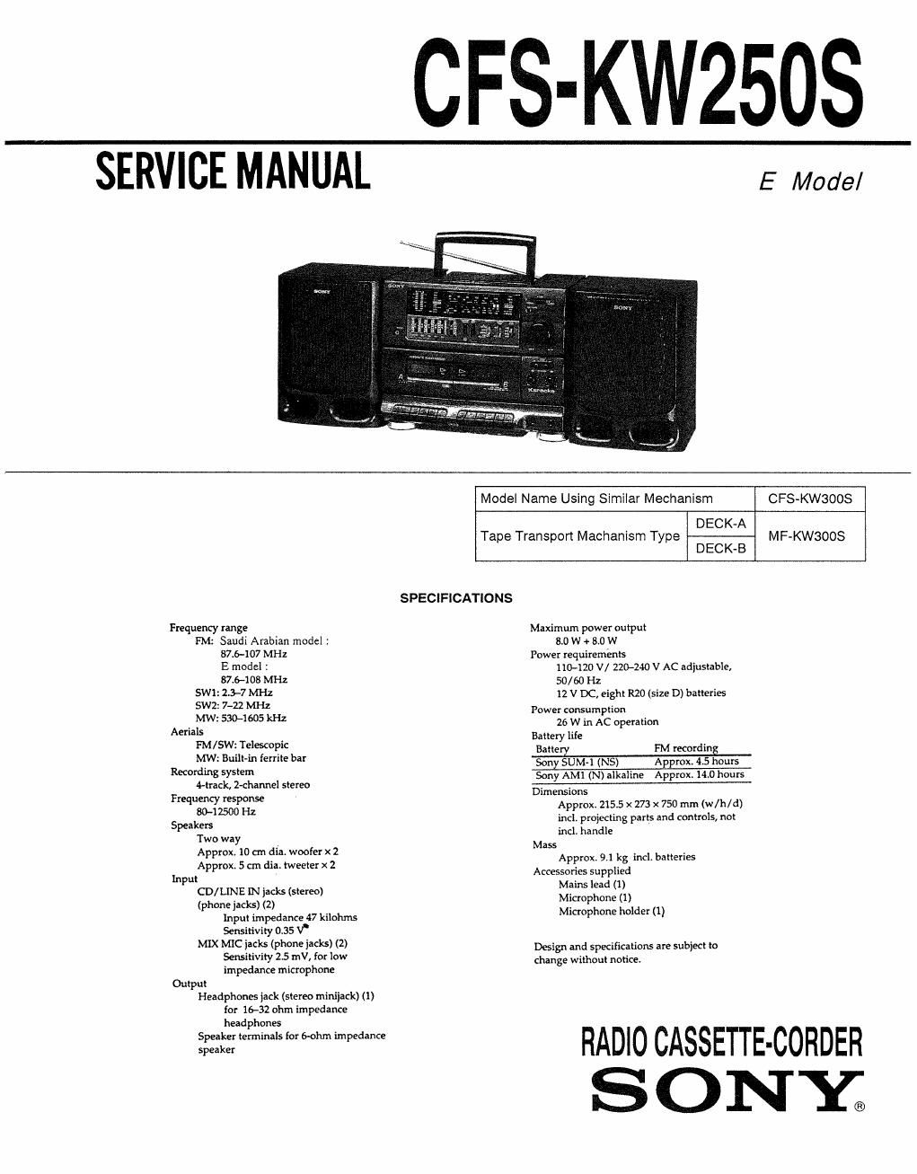
sony cfs kw 250 s service manual

Extracted text from sony cfs kw 250 s service manual (Ocr-read)


Page 1

SERVICE MANUAL

CFS-KW2503

E Model

Frequency range

FM: Saudi Arabian model :
87.6-107 MHz
E model 1
87.6403 MHz

SW1: 2.3-7 MHz

5W2: 7-22 MHz

MW: 530-1605 kHz

Aerials
FM/SW' elescopic
MW: Built-in ferrite bar
Recording system
4-t-rack. 2-channel stereo
Frequency response
80-] 2500 Hz
Speakers

Two way

Approx. 10 cm dia. woofer x 2

Approx. 5 cm dia. tweeter x 2

input

CD/ LINE IN jacks (stereo)

(phone jacks) (2)

Input impedance 47 kilohms
Sensitivity 0.35 v'

MIX MIC jacks (phone jacks) (2)
Sensitivity 25 mV, for low
impedance microphone

Output

Headphones jack (stereo minijack) (i)
for 1&32 ohm impedance
headphones

Speaker terminals for 6-ohm impedance

speaker

Model Name Using Similar Mechanism CF8-KW3OOS
DECK-A

Tape Transport Machanism Type MF-KWBOOS
DECK-B

SPECIFICATIONS

Maximum power output
8.0 W + 8.0 W
Power requirements
110-120 V/ 220-240 V AC adjustable,
50/ 60 Hz
12 V DC, eight R20 (size D) batteries
Power consumption
26 W in AC operation

Battery life
Barre FM recordin
Son SUM-i (NS) A mm 4.5 hours

Sony AMI (N) alkaline Approxr 14.0 hours

Dimensions
Approx. 215.5 x 273 x 750 mm (w/h/d)
inclr projecting parts and controls, not
incl, handle
Mass
Approx. 9.1 kg incl. batteries
Accessories supplied
Mains lead (1)
Microphone (i)
Microphone holder (1)

Design and specifications are subject to
change without notice,

RADIO CASSETTE-CORDER

SONY;

Page 2

TABLE OF CONTENTS

Section Title Page

Specifications ~~~~~~~~~~~~~~~~~~~~~~~~~~~~~~~

1.

GENERAL
Looking at the Controls ~~~~~~~~~~~~~~~

. DIAL POINTER INSTALLATION .............................. 4

ADJUSTMENTS
3-1 Mechanical Adjustments»
3-2. Electrical Adjustments -~

DIAGRAMS
4~lr Printed Wiring Boards
4-2. Schematic Diagram

EXPLODED VIEWS
5-1, General Section-l H
5-2 General Section-2 --
5-3i Mechanism Deck Section~1
5-4. Mechanism Deck Section-2
5-5. Mechanism Deck Section-3
5-6 Speaker Sectionm


ELECTRICAL PARTS LIST ~~~~~~~~~~~~~~~~~~~~~~~~~~~~~~~~ 28

0 HOW TO CHANGED THE CERAMIC FILTERS

This model is used three ceramic filters of CFI, CFZ and CF31

You must used same type of color marked ceramic filters in
order to meet same specifications

Therefore, the ceramic filter must changed three pieces
together since its supply three pieces in on package as

a spare parts,

mark Wk mark £33?ch
0 red 10.70MHz
CF1, 2 blue 10,67MHz
orange 10.73MHZ

I I I black 10.64MH2
white 1076MH2

SAFETY-RELATED COMPONENT WARNING"

COMPONENTS IDENTIFIED BY MARK A 0R DOTTED
LINE WITH MARK A ON THE SCHEMATIC DIAGRAMS
AND IN THE PARTS LIST ARE CRITICAL TO SAFE
OPERATION. REPLACE THESE COMPONENTS WITH
SONY PARTS WHOSE PART NUMBERS APPEAR AS
SHOWN IN THIS MANUAL OR IN SUPPLEMENTS PUB-
LISHED BY SONY.