Sony cfs e 15 service manual

This is the 21 pages manual for sony cfs e 15 service manual.
Read or download the pdf for free. If you want to contribute, please upload pdfs to audioservicemanuals.wetransfer.com.

Page: 1 / 21
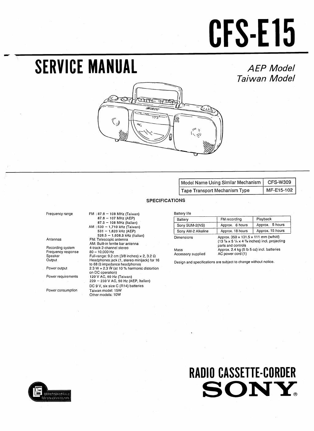
sony cfs e 15 service manual

Extracted text from sony cfs e 15 service manual (Ocr-read)


Page 1

(IFS-E15

SERVICE MANUAL AEP Model

Taiwan Model

Model Name Using Similar Mechanism CFS-W309
Tape Transport Mechanism Type MF

SPECIFICATIONS

Frequency range FM :816 - 103 MHz (Taiwan) Banery "'9
2;: 3; :2 551 ) Battery FM recording Playback
. - 1 2 la ian
AM .530 _ 1.710 kHz (raiwan) Sony SUM-2(NS) Approx. 6 hours Approx. 5 hours
531 - 1.620 kHz (AEP) Sony AMA2 Alkaline Approx. 18 hours Approx. 15 hours
5235 - 1,606.5 kHz (Italian) D" .
. - rmensions Approx 350 x 181.5 x 111 mm (w/hld)
Anrennas FM: TelescopIc-antenna (13 l. x 5 II x 4 /- inches) incl. projecting
> AM. Built-1n Iernie bar anlenna pans and conirols
:gfifiggfefigse gfififiggafle' 9' Mass Approx. 2.4 kg (5 lb 5 oz) incl. batteries
Speaker Full-range: 9.2 cm (3/8 inches) x 2, 3.2 Q Accessory SUppIIEd AC power cord (1)
Output Headphones iack (1. stereo miniiack) for 16 . . . . . . .
(o 68 fl impedance headphones Design and specrllcauons are subjecl 10 change wnhour notice.
Power ouipul 2.3 W + 2.3 W (a! 10 % harmonic dislonion
on DC operation)
Power requirements 120 V AC, 30 Hz (Taiwan)

220 - 230 V AC. 50 Hz (AEP. Italian)

DC 9 V. six size C (R14) baneries
Power consumption Taiwan model: 15W

Other models: 10W

RADIU CASSETTE-BORDER
SONE

Page 2

TABLE OF CONTENTS Model ldentlflcatlon

Section ILE Pa :5 S ONW
. . . MODEL NO. CFS-E15

Speclficauons .................................. 1

RADIO CASSETTE-CORDER
1. GENERAL WW
Pans Identification .............................. 2
2. DISASSEMBLY ......................... 3
3. MECHANICAL ADJUSTMENTS --------- 5

AEP, Italian model: AC 220 - 230 V ~50 Hz 10 W

4. ELECTRICAL ADJUSTMENTS .......... 5 Taiwan model: AC 120 V ~60 Hz
4-]. Tape Recorder Section -------- v ----------- 5
4.2, Tuner Section .......... . ................. 6

5. DIAGRAMS

5.1. Block Diagram ........................... 7
5-2. Printed Wiring Boards --------------------- 15
5-3. Schematic Diagram ....................... 15
6. EXPLODED VIEWS .................... 20
7. ELECTRICAL PARTS LIST ------------ 24

SECTION 1

GENERAL

Parts Identlflcatlon

FUNCTION selector
TONE knob

OPR/BATI' indicator
Bullt-in microphone
DIRECTION buttons
Tape operation button

VOLUME knob

TUNING knob
PHONES iack a-u

FM/AM MODE switch _>

Ac IN jack

CASSETTE HOLDER

DIR MODE switch