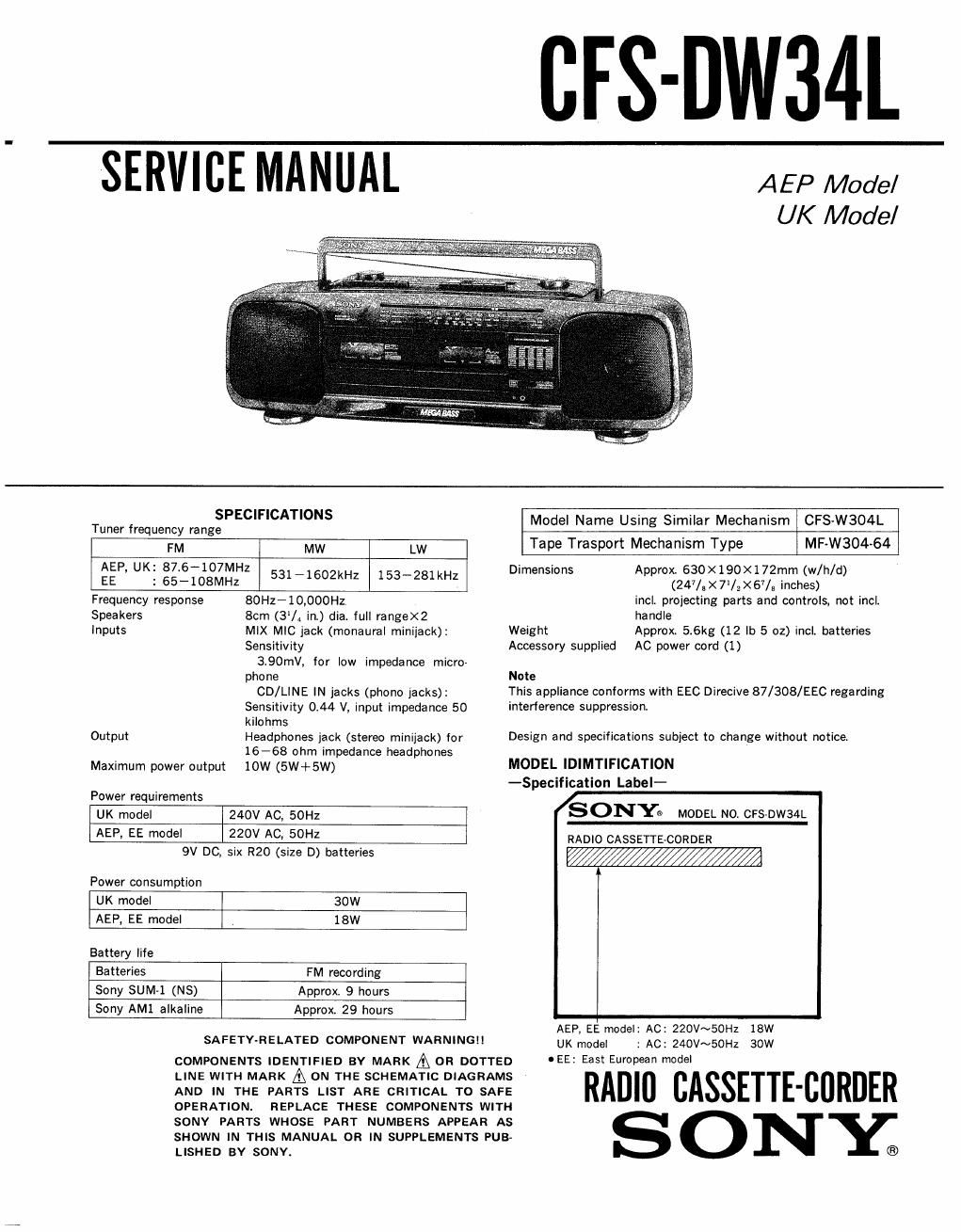
Sony cfs dw 34 l service manual
This is the 17 pages manual for sony cfs dw 34 l service manual.
Read or download the pdf for free. If you want to contribute, please upload pdfs to audioservicemanuals.wetransfer.com.
Extracted text from sony cfs dw 34 l service manual (Ocr-read)
Page 1
CFS-DW34L
SERVICE MANUAL
AEP Mode/
UK Model
SPECIFICATIONS
Tuner frequency range
FM
MW LW
AEP. UK: 87,6-107MHZ
EE : 65-108MHZ
531 - 1602kHz 153-281 kHz
Frequency response
Speakers
Inputs
Output
Maximum power ontput
Power requirements
80Hz-10,000Hz
8cm (3% in.) dia. full rangeXZ
MIX MIC jack (monaural minijack):
Sensitivity
3.90mV, tor low impedance micro-
phone
CD/LINE IN jacks (phono jacks):
Sensitivity 0.44 V, input impedance 50
kilohms
Headphones jack (stereo minijack) for
16-68 ohm impedance headphones
10W (5W+5W)
UK model
240V AC, 50Hz
AEP, [E model
220V AC, 50H:
9V DC,
Power consumption
six R20 (size D) batteries
UK model 30W
AEP, EE model 18W
Battery life
Batteries FM recording
Sony SUle (NS)
Approx. 9 hours
Sony AMI alkaline
Approx. 29 hours
SAFETY-RELATED COMPONENT WARNINGII
COMPONENTS IDENTIFIED BV MARK A OR DOTTED
LINE WITH MARK A ON THE SCHEMATIC DIAGRAMS
AND IN THE PARTS LIST ARE CRITICAL TO SAFE
REPLACE THESE COMPONENTS WITH
SONY PARTS WHOSE PART NUMBERS APPEAR AS
SHOWN IN THIS MANUAL OR IN SUPPLEMENTS PUB«
OPERATIONI
LISHED
BY SONY.
Model Name Using Similar Mechanism
CFSvW304-L
Tape Trasport Mechanism Type
MF-W304-64
Dimensions
Weig ht
Accessory supplied
Note
Approx 630x190X 1 72mm (w/h/d)
(247/5X7/2><67/3 inches)
incl projecting parts and controls, not incl.
handle
Approx, 5.6kg (12 lb 5 oz) incl. batteries
AC power cord (1)
This appliance conforms with EEC Direcive 87/308/EEC regarding
interference suppression,
Design and specifications subject to change without notice
MODEL IDIMTIFICATION
-Specification Label-
SONYQ
RADIO CASSETTECORDER
WWW
MODEL N0. CFSDW34L
AEP, EE model: AC: 220V~50Hz 18W
UK model
: AC: 240V~50Hz 30W
oEE: East European model
RADIO BASSETTE-CURDER
S ONY;
Page 2
SECTION 1
CFS-DW34L
DISASSEMBLY
Note: Follow the disassembly procedure in the numerical order given,
1-1. REMOVAL OF FRONT CABINET ASSEMBLY
0 Remove the battery case lid shown by arrow ®,
0 Remove the front cabinet assy shown by arrow (B)
4 Connector (CNP352)
1-2. REMOVAL OF MD ASSEMBLY
0 Connector (CNP301)
o Connector (CNP302)
Connector (CNP354)
0 Remove the MD assy
shown by arrow