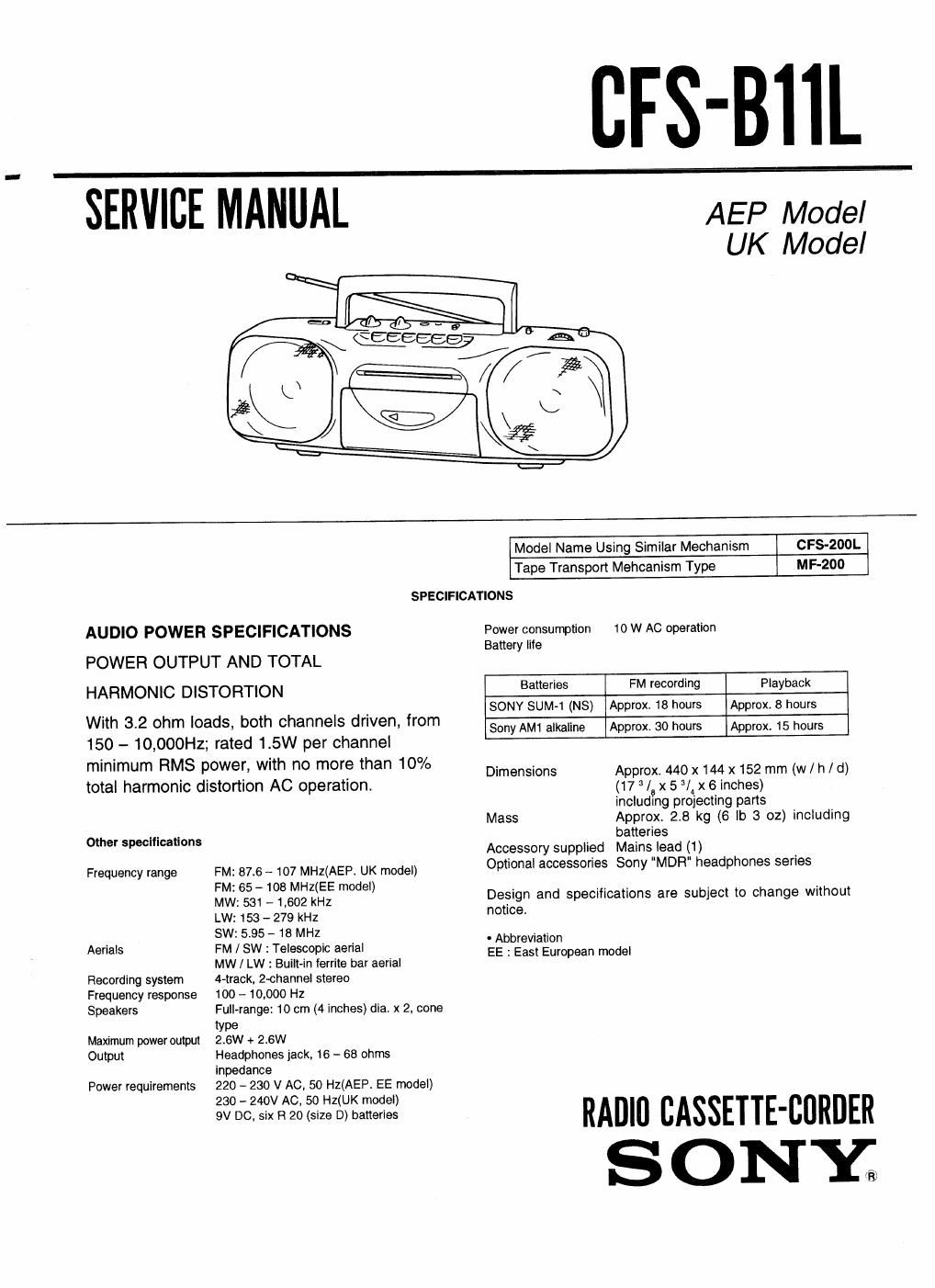
Sony cfs b 11 l service manual
This is the 21 pages manual for sony cfs b 11 l service manual.
Read or download the pdf for free. If you want to contribute, please upload pdfs to audioservicemanuals.wetransfer.com.
Extracted text from sony cfs b 11 l service manual (Ocr-read)
Page 1
_ .CFSTBHL
' SER_VICE M'ANUTlL '
AEP Model
UK Model
AUDIO POWER SPECIFICATIONS
POWER OUTPUT AND TOTAL
HARMONIC DISTORTION
With 3.2 ohm loads, both channels driven, from
150 - 10,000Hz; rated 1.5W per channel
minimum RMS power, with no more than 10%
total harmonic distortion AC operation.
Other specifications
Frequency range
Aerials
Recording system
Frequency response
Speakers
Maximum power output
Output
Power requirements
Model Name Using Similar Mechanism CFS-200L
Tape Transport Mehcanism Type MF-zoo
SPECIFICATIONS
Power consumption 10 W AC operation
Battery life
Batteries FM recording Playback
FM: 87.6 -- 107 MHZ(AEP. UK model)
FM: 65 - 103 MHZ(EE model)
MW: 531 - 1,602 kHz
LW: 153 - 279 kHz
SW: 5.95 - 18 MHz
FM / SW : Telescopic aerial
MW / LW : Bullt-ln ferrite bar aerial
4-track, 2-channel stereo
100 -- 10,000 HZ
Full-range: 10 cm (4 inches) dia. x 2, cone
type
2.6W + 2.6W
Headphones jack. 16 - 68 ohms
lnpedance
220 - 230 V AC, 50 HZ(AEP. EE model)
230 - 240v AC, so HZ(UK model)
9V DC, six R 20 (size D) batteries
SONY SUM»1 (NS) Approx. 18 hours Approx. 8 hours
Sony AM1 alkaline Approx. 30 hours Approx. 15 hours
Dimensions Approx. 440 x 144 x 152 mm (w / h / d)
(17 /a x 5 9/ x 6 inches)
including projecting parts
Mass Approx. 2.8 kg (6 lb 3 02) including
batteries
Accessory supplied Mains lead (1)
Optional accessories Sony "MDR' headphones series
Design and specifications are subject to change without
notice.
' Abbreviation
EE : East European model
RAlllfl BASSETIE-CflRDER
S ONY
Page 2
TABLE OF CONTENTS
Sectign Title Page
1. GENERAL
Locations of Control .
2. DISASSEMBLY ....................................................... 5
3. MECHANICAL ADJUSTMENTS ............................. 6
4. ELECTRICAL ADJUSTMENTS
5. DIAGRAMS
5-1. Printed Wiring Board - Tuner Section -
5-2. Schematic Diagram - Tuner Section -
5-3. Semiconductor Lead Layouts ............
5-4. Printed Wiring Board - Audio Section -
5-5. Schematic Diagram - Audio Section - ..
6. EXPLODED VIEWS
6-1. Front Cabinet Section ..
6-2. Rear Cabinet Section ..
6-3t Mechanism Deck Block Section (1)
6-4. Mechanism Deck Block Section (2)
7. ELECTRICAL PARTS LIST ..................................... 21
SAFETY-RELATED COMPONENT WARNING !!
COMPONENTS IDENTIFIED BY MARK A OR DOTTED
LINE WITH MARK A ON THE SCHEMATIC DIAGRAMS
AND IN THE PARTS LIST ARE CRITICAL TO SAFE OP-
ERATION. REPLACE THESE COMPONENTS WITH
SONY PARTS WHOSE PART NUMBERS APPEAR AS
SHOWN IN THIS MANUAL OR IN SUPPLEMENTS PUB-
LISHED BY SONY.