Sony cfs 828 s service manual

This is the 36 pages manual for sony cfs 828 s service manual.
Read or download the pdf for free. If you want to contribute, please upload pdfs to audioservicemanuals.wetransfer.com.

Page: 1 / 36
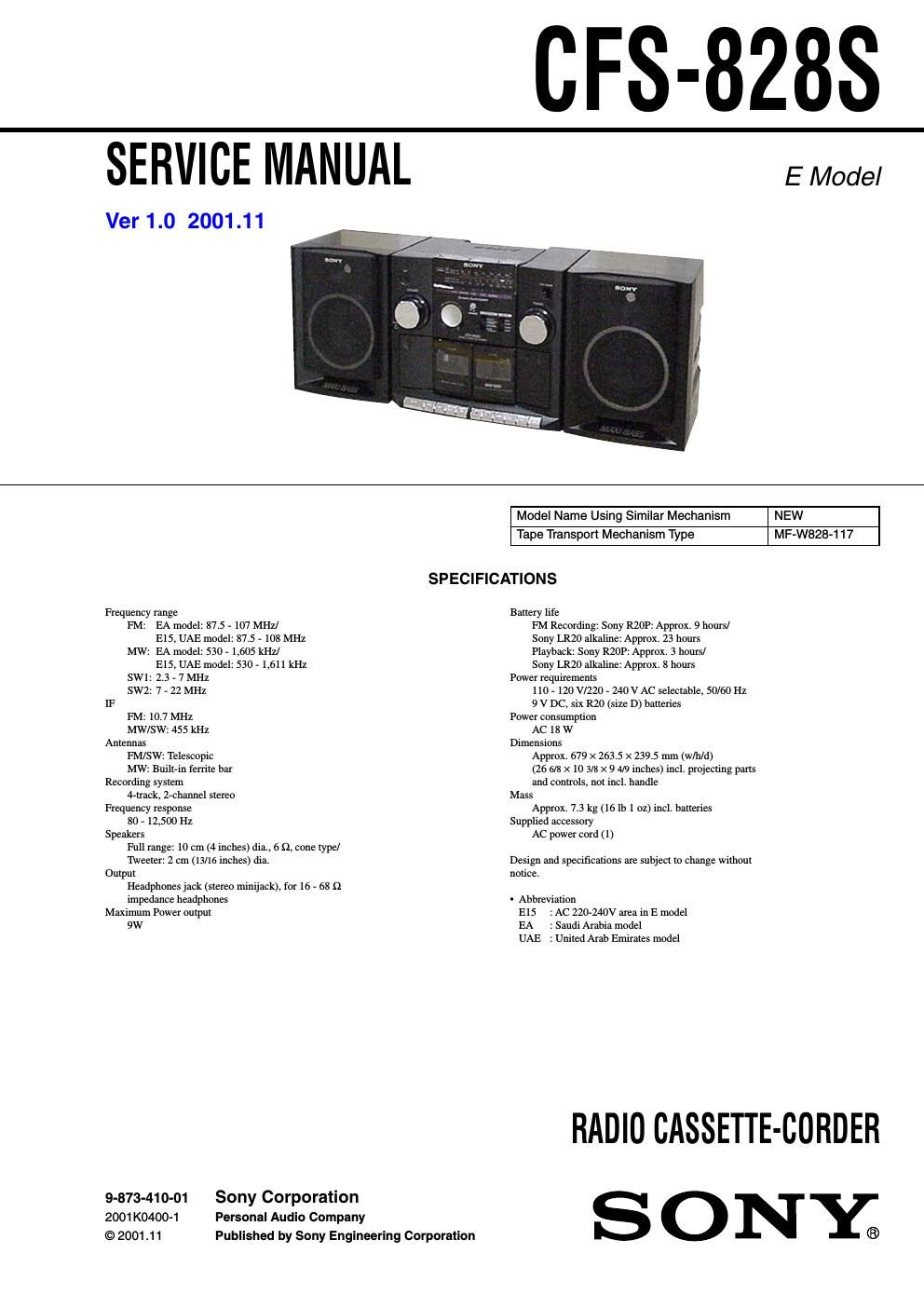
sony cfs 828 s service manual

Extracted text from sony cfs 828 s service manual (Ocr-read)


Page 1

(IFS-8288

SERVICE MANUAL EModel

Ver 1.0 2001.11

Model Name Using Similar Mechanism NEW
Tape Transpori Mechanism Type MF-W828-117
SPECIFICATIONS

Frequency range Battery life

FM: EA model: 87.5 , 107 MHz/ PM Recording: Sony R20P: Approx. 9 hours/

E15. UAE model: 87.5 , 108 MHz Sony LR20 alkaline: Approx. 23 hours
MW: EA model: 530 . 1,605 kHz] Playback: Sony RZOP: Approx. 3 hours/
E15. UAE model: 530 , 1.611 kHz Sony LR20 alkaline: Approx. 8 hours

SW1: 2.3 . 7 MHz Power requirements

SW2: 7 , 22 MHz 110 . 120 V/220 . 240 V AC selectable. 50/60 Hz
IF 9 v DC, six R20 (size D) batteries

FM: 10.7 MHz Power consumption

MW/SW: 455 kHz AC 18 w
Antennas Dimensions

FM/SW: Telescopic Approx. 679 x 263.5 x 239.5 mm (w/h/d)

Mw: BuilHn ferrite bar (26 6/8 x 10 3/2; x 9 4/9 inches) incl. projecting pans
Recording system and controls, not incl. handle

4ruack, Zechannel stereo Mass
Frequency response Approx. 7.3 kg (16 lb 1 oz) incl. batteries

80 . 12,500 Hz Supplied accessory
Speakers AC power cord (1)

Full range: 10 cm (4 inches) dia.. o a, cone type/

Tweeter: 2 cm (13/16 inches) dia. Design and specifications are subject to change without
Output notice.

Headphones jack (stereo minijack). for 16 . 68 £2

impedance headphones - Abbreviaijon
Maximum Power output E15 : AC 2207mv area in E model

9W EA - Saudi Arabia model

UAE : Uniied Arab Emirates model

RADIO CASSETTE-CORDER
9-873-410-01 Sony Corporation S O N Y
2001K0400-1 Personal Audio Company
© 2001.11 Published by Sony Engineering Corporation ®

Page 2

CFS-828S

TABLE OF CONTENTS

1. GENERAL ............................................................... 3
2. DISASSEMBLY

2-1. Cabinet (Rear) Assy ............................................. 4
2-2. Power Board ..... .5
2-3. Mechanism Deck 5
2-4. H/P, LEDZ, Maxi Bass, VOL and Main Boards . 6
2-5. FIT and Tuner Boards .. 6
2-6. Jog and LEDl Boards . 7
2-7. REC SW Board, Belt and Motor Assy (W) (M301) . 7
3. DIAL POINTER SETTING ............................................. 8
4. MECHANICAL ADJUSTMENTS ................................. 9

5. ELECTRICAL ADJUSTMENTS
Tape Section
Tuner Section ..


6. DIAG RAMS

6-1. Circuit Boards Location
6-2. Block Diagram ..
6-3. Printed Wiring Boards # Tuner Section -
6-4. Schematic Diagram _ Tuner Section -.
6-5. Printed Wiring Boards # Main Section - .
6-6. Printed Wiring Boards 7 Power Section e
6-7. Schematic Diagram _ Main Section (1/2)
6-8. Schematic Diagram _ Main Section (2/2) - ...................... 19


7. EXPLODED VIEWS

7-1. Cabinet (Rear) Section . 21
7-2. Cabinet (Front) Section-1 . 22
7-3. Cabinet (Front) Section-2 . 23
7-4. Mechanism Deck Section-l . 24
7-5. Mechanism Deck Section-2 . 25
7-6. Mechanism Deck Section-3 . 26
7-7. Speaker Section ............... . 27

8. ELECTRICAL PARTS LIST ......................................... 28

Notes on Chip Component Replacement

- Never reuse a disconnected chip component.

0 Notice that the minus side of a tantalum capacitor may he dam-
aged by heat.

SAFETY-RELATED COMPONENT WARNINGII

COMPONENTS IDENTIFIED BY MARK A OR DOTTED LINE
WITH MARK A ON THE SCHEMATIC DIAGRAMS AND IN
THE PARTS LIST ARE CRITICAL TO SAFE OPERATION.
REPLACE THESE COMPONENTS WITH SONY PARTS WHOSE
PART NUMBERS APPEAR AS SHOWN IN THIS MANUAL OR
IN SUPPLEMENTS PUBLISHED BY SONY.

2