Sony cfs 229 service manual

This is the 20 pages manual for sony cfs 229 service manual.
Read or download the pdf for free. If you want to contribute, please upload pdfs to audioservicemanuals.wetransfer.com.

Page: 1 / 20
sony cfs 229 service manual

Extracted text from sony cfs 229 service manual (Ocr-read)


Page 1

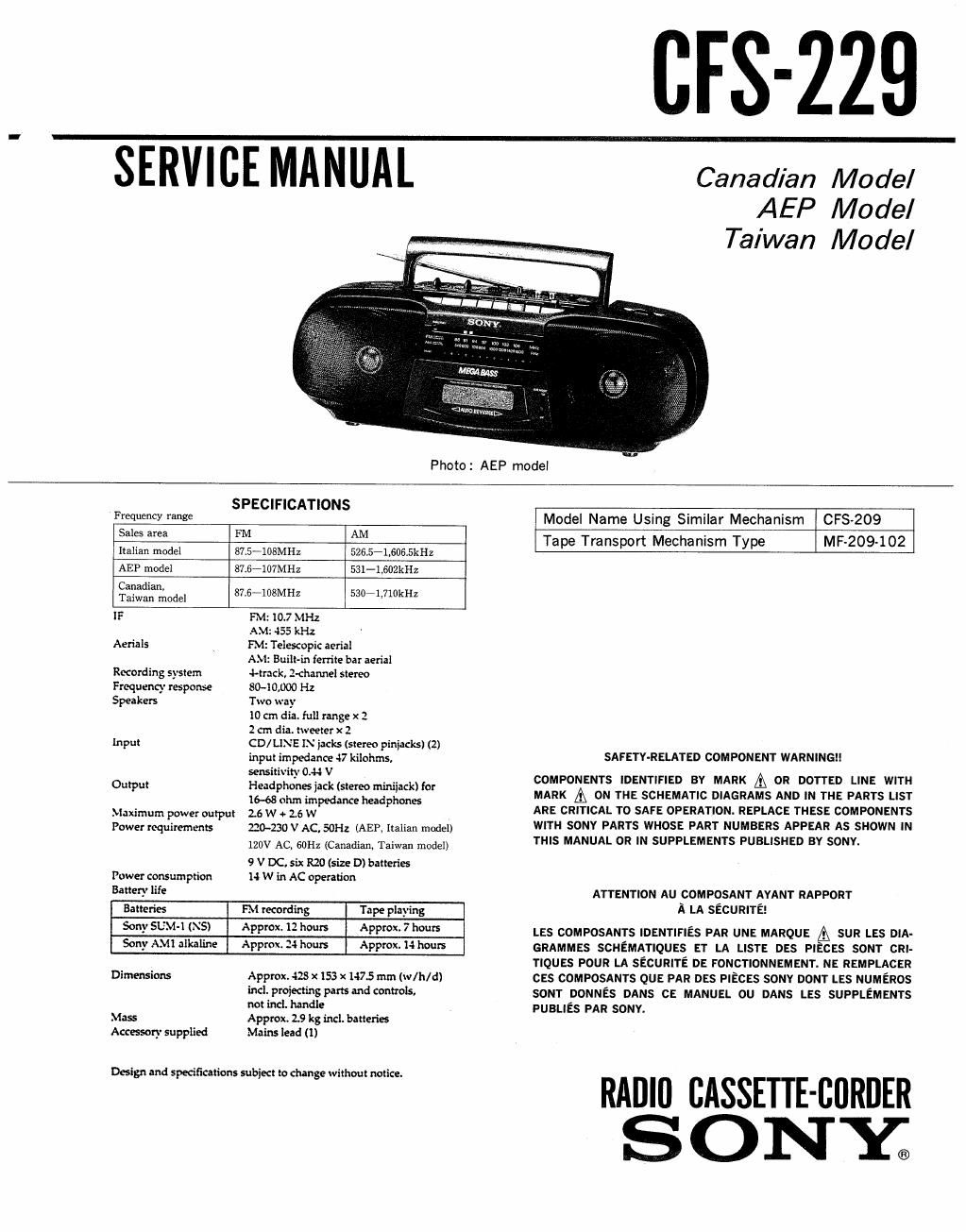
SERVICE MANUAL

BIS-229

Canadian Model
AEP Model
Taiwan Model

: AEP model

P ho to
SPECIFICATIONS
Frequency range
Sales area FM AM
Italian model 87.5-108MHZ 526.5'-1,606.5kl-lz
AEP model 87.67107MH2 531-l,502kHz
Canadian,
Taiwan model 87.6-108MH2 530-1,710kHz
IF FM: 10.7 MHz
A 55 kHz
Aerials PM Telescopic aerial

Recording system
Frequency response
Speakers

input

Output

A. . Built-in ferrite bar aerial

rack, l-channel stereo

$040,000 Hz

Two way

10 an die. full range x 2

2 cm dia. tweeter x 2

CD/LINE I.\' jar-ls (stereo piniacksl (2)
input impedance 47 kilohms.
sensitivity 0.44 V

Headphones jack (stereo miniiackl for
16-68 ohm impedance headphones

Maximum power output 2.6 W + 2.6 w

Power requirements

220-230 V AC, EH2 (AEP, Italian model)
120V AC, 60112 (Canadian. Taiwan model)
9 V DC, six R20 (size D) batteries

Power consumption 14 W in AC operation
Battery life
Batteries FM recording Tape playing
Sony SUM-l (NS) Approx. 12 hours Approx. 7 hours
Sony AMT alkaline Approx. 24 hours Approx. 14 hours
Dimensions Approx. 428 x 153 x 147.5 mm (w/h/d)
incl. projecting parts and controls.
not ind. handle
Mass Approx. 2.9 kg incl. batteries

Accessory supplied

Mains lead (1)

Design and specifications subject to change without notice.

Model Name Using Similar Mechanism CFS-209
Tape Transport Mechanism Type MF-209-102

SAFETY-RELATED COMPONENT WARNING

COMPONENTS IDENTIFIED BY MARK & OR DOTTED LINE WITH
MARK A ON THE SCHEMATIC DIAGRAMS AND IN THE PARTS LIST
ARE CRITICAL T0 SAFE OPERATION. REPLACE THESE COMPONENTS
WITH SONY PARTS WHOSE PART NUMBERS APPEAR AS SHOWN IN
THIS MANUAL OR IN SUPPLEMENTS PUBLISHED BY SONY.

ATTENTION Au composmr AYANT RAPPORT
A LA SECURITE!

LES COMPOSANTS IDENTIFIES PAR UNE MARQUE A sun as DIA-
GRAMMEs SCHEMATIQUES ET LA LISTE DES PIECES sour CRI-
TIQUES POUR LA sEcunlre DE FONCTIONNEMENT. NE REMPLACER
cas COMPOSANTS QUE PAR DES PIECES sonv DONT LES NUMERos
som DONNES DANS CE MANUEL ou DANS LES SUPPLEMENTS
PUBLIEs PAR souv.

RADIO CASSETTE-CURDER
S 0 NY;

Page 2

MODEL IDENTIFICATION TABLE OF CONTENTS
-Label Model Number-

/- Section Title
SONY® ,
MODEL Noi CFS-229 1. DIAL POINTER SETTING

1-1i Dial Pointer Setting ....................
RADIO CASSETTE-CORDER

I IIIIIIIIIIII 2. MECHANICAL ADJUSTMENTS ..........

3. ELECTRICAL ADJUSTMENTS
3»1. Tape Recorder Section ................
3»2. Tuner Section .........................

4. DIAGRAMS
4-1, Printed Wiring Board-Tuner Section-
4-2. Semiconductor Lead Layouts ............

4-3. Schematic Diagram-Tuner Section- . t
4-4. Printed Wiring Boards-Audio Section-

Canadian, Taiwan model: Ac: 120V 60Hz 14W 4-5. Schematic Diagram-Audio Section .....
AEP, Italian model : AC: 220-230V~50Hz 14W

Italian model only

5. EXPLODED VIEWS

5-1i Front Cabinet Section iiiiiiiiiiiiiiiii
5-2. Rear Cabinet Section ...................
5-3. Mechanism Deck Section (1) ...........
5-4. Mechanism Deck Section (2) ...........

6. ELECTRICAL PARTS LIST iiiiiiiiiiiii

Page

.......... 2

.......... 3

.......... 3
.......... 4

.......... 6
iiiiiiiiii 6
.......... 7

........ 10
......... 13

......... 16
......... 17
,,,,,,,,, 18
......... 20

......... 21

SECTION 1
DIAL POINTER SETTING

1-1- DIAL POINTER SETTING OSet the pointer to Iigure position

direction button direction button

l<-


9 BVTP3X14 upper side View

8 '% k- pointer
29
\\

0 Turn the tuning knob
fully in the direction
oI arrow

0 Set the dial chassis

__2_

OBVTPSXIA