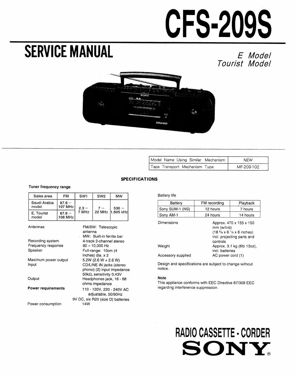
Sony cfs 209 s service manual
This is the 21 pages manual for sony cfs 209 s service manual.
Read or download the pdf for free. If you want to contribute, please upload pdfs to audioservicemanuals.wetransfer.com.
Extracted text from sony cfs 209 s service manual (Ocr-read)
Page 1
CFS-2098
SERVICE MANUAL
E Model
Tour/st Model
Model Name Using Simiiar Mechanism NEW
Tape Transport Mechanism Type MF-2097102
SPECiFICATIONS
Tuner frequency range
Sales area FM sw1 sw2 MW Battery '9
Saudi Arabia 57.6 -- Battery FM recording Playback
made. 107 MHZ 72:4}; 227in i 232 k-H sony SUMq (NS) 12 hours 7 hours
E. Tourist 87.6 - 2 Z , Z . 4
model 108 MHz Sony AM 1 24 hours 1 hours
Dimensions Approx. 470 x 155 x 150
Antennas FM/SW: Telescopic mm (w/h/d)
Recording system
Frequency response
Speaker
Maximum power output
Input
Output
Power requirements
antenna
MW: Built-in ferrite bar
4-track 2-channei stereo
80 - 10,000 Hz
Full-range: 10cm (4
inches) dia. x 2
52W (26 W + 2.6 W)
CD/LiNE iN jacks (stereo
phone) (2) input impedance
SOkQ, sensitivity 0,43V
Headphones jack. 16 - 68
ohms impedance
110 - 120v. 220 - 240v AC
adjustable, 50/60Hz
SV 00, six R20 (size D) batteries
Power consumption
14W
(18 5/3 x 6 /e x 6 inches)
incl. projecting parts and
controls
Weight Approx. 3.1 kg {Gib 1302),
incl. batteries
Accessory supplied AC power cord (1)
Design and specifications are subject to change without
notice.
Note
[This appliance conforms with EEC Directive 87/308 EEC
regarding interference suppression.
RADIOCASSETTE-CORDER
S ON Y®
Page 2
CPS-209$
TABLE OF CONTENTS
Section Title Page
Specifications ........................................................... 1
1. GENERAL
Location and Function of Controls- ~3
Tape Playback ......................... ..4
Listening to the Radio ............................................... 4
2. DIAL POINTER INSTALLATION
Dial pointer and Dir Indicator Installation --------------------- 5
3. ADJUSTMENTS
3-1. Mcchanical Adjustments ----------------------------------- 6
3-2. Electrical Adjustments -------------------------------- 6
4. DIAGRAMS
4-1. Printed Wiring Boards ~ 10
4-2. Schematic Diagram ~~ -- 13
5. EXPLODED VIEWS .............................................. 17
6. ELECTRICAL PARTS LIST ~~~~~~~~~~~~~~~~~~~~~~~~~~~~~~~~~~~ 21
SAFETY-RELATED COMPONENT WARN INGl!
COMPONENTS IDENTIFIED BY MARK A OR DOTTED
LINE WITH MARK A ON THE SCHEMATIC DIAGRAMS
AND IN THE PARTS LIST ARE CRITICAL T0 SAFE
OPERATION. REPLACE THESE COMPONENTS WITH
SONY PARTS WHOSE PART NUMBERS APPEAR AS
SHOWN IN THIS MANUAL OR IN SUPPLEMENTS PUB-
LISHED BY SONY.