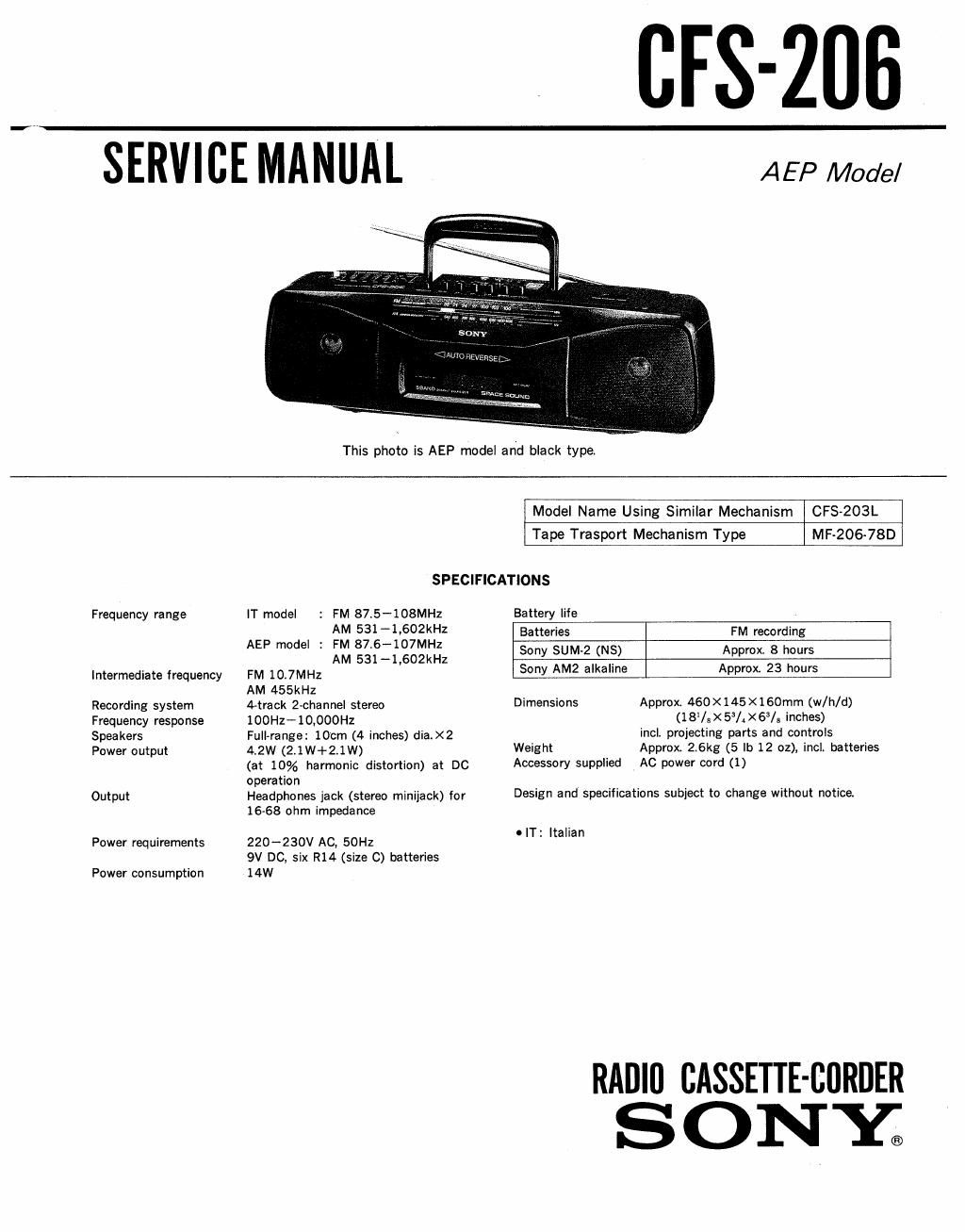
Sony cfs 206 service manual
This is the 19 pages manual for sony cfs 206 service manual.
Read or download the pdf for free. If you want to contribute, please upload pdfs to audioservicemanuals.wetransfer.com.
Extracted text from sony cfs 206 service manual (Ocr-read)
Page 1
CFS-ZUB
SERVICE MANUAL
This photo is AEP model and black type,
AEP Model
Frequency range
Intermediate frequency
Recording system
Frequency response
Spea kers
Power output
Output
Power requirements
Power consumption
Model Name Using Similar Mechanism CFS-ZO3L
Tape Trasport Mechanism Type MF»206-7SD
SPECIFICATIONS
IT model : FM 87.5~108MH2 Battery life
AM 531-1v602kHZ Batteries FM recording
AEP m°de' i m 8573-16:11%':;';2 Sony sthz (NS) Approx 8 hours
FM 10.7MHz ' Sony AM2 alkaline Approx. 23 hours
AM 455kHz
4-track 2-channel stereo
IOOHz- 10,000Hz
Full-range: 100m (4 inches) diaiX2
4.2W (2.1W+2.1W)
(at 10% harmonic distortion) at DC
operation
Headphones jack (stereo miniiack) for
16-68 ohm impedance
220-230V AC, 50Hz
9V DC, six R14 (size 0) batteries
14W
Dimensions
Approx 460 X 145 X 1 60mm (w/h/d)
(1 8% X 53/. ><6/8 inches)
incl. projecting parts and controls
Weight
Accessory supplied AC power cord (1)
Approx. 2.6kg (5 lb 12 oz), incl. batteries
Design and specifications subject to change without notice.
o IT: Italian
RADIO CASSETTE-CBRDER
S O NYE)
Page 2
CPS-206
TABLE OF CONTENTS
Section Title fizgg
1. DISASSEMBLY
1-1. Removal of Cassette Holder .................... 3
1-2. Dial Pointer Setting ............................ 3
2. MECHANICAL; ADJUSTMENTS .................... 4
3. ELECTRICAL ADJUSTMENTS
3-1. Tape Recorder Section ........................ 4
3-2. Tuner Section .................................. 5
4. DIAGRAMS
4-1.
4-2.
4-3.
4-4.
4-5.
Printed Wiring Board -Tuner Section- ........ 7
Schematic Diagram -Tuner Section- .......... 8
Semiconductor Lead Layouts .................. 10
Schematic Diagram -Audio Section- .......... 11
Printed Wiring Boards -Audio Section-
Section Title nge
5. EXPLODED VIEWS
5-1. Front Cabinet Section ........................ 15
5-2. Rear Cabinet Section .......................... 16
5-3. Mechanism Deck Section (1) .................. 17
5-4. Mechanism Deck Section (2) .................. 18
5-5. Mechanism Deck Section (3) .................. 19
6. ELECTRICAL PARTS LIST ...................... 20