Sony cfd z 500 550

This is the 9 pages manual for sony cfd z 500 550.
Read or download the pdf for free. If you want to contribute, please upload pdfs to audioservicemanuals.wetransfer.com.

Page: 1 / 9
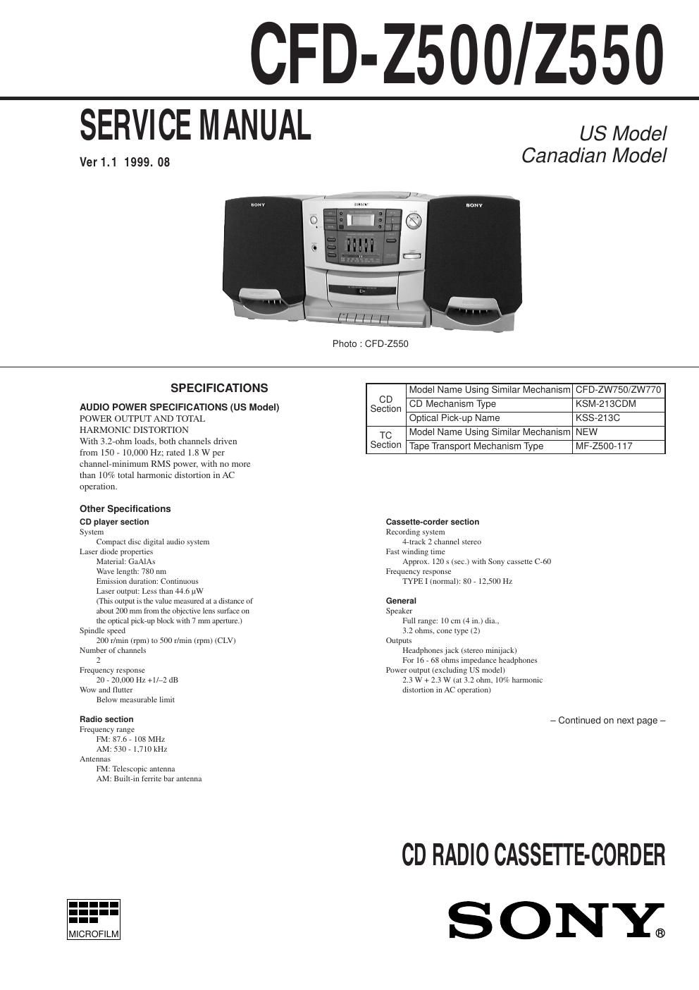
sony cfd z 500 550

Extracted text from sony cfd z 500 550 (Ocr-read)


Page 1

CFD-Z500/2550

SERVICE M AN UAL us Model

Ver 1.1 1999. 08 Canadian Model

Photo : CFD-ZSSO

SPECIFICATIONS Model Name Using Similar Mechanism CFD-ZW750/ZW770
CD -
AUDIO POWER SPECIFICATIONS (us Model) Section CD MEChan'sm Type KSM'23CDM
POWER OUTPUT AND TOTAL Optical Pick-up Name KSS-213C
HARMONIC DISTORTION Model Name Using Similar Mechanism NEW
. . . . TC
Wflh 3.2-ohm loads, both channels driven Section Tape Transport Mechanism Type MF-2500-117

from 150 - 107000 Hz; rated 1.8 W per
channel-minimum RMS power. with no more
than 10% total harmonic dislonion in AC
opernlion.

Other Specifications
CD player section
Sysiem
Compact disc digital audio syslem
Laser diode properties
Material: GaAlAs
Wave length: 780 nm
Emission duration: ConmmOuS
Laser output: Less than 44 6 iiw
(This output is the value measured at a distance of
about 200 min from the objecltve lens surface on
the optical pICkrup block with 7 mm aperture.)
Spindle speed
200 r/tnin (rpm) to 500 r/tntn trpin) (CLV)
Number of channels
2
Frequency response
20 , 20,000 Hz +l/72 dB
Wow and flutter
Below measurable liintt

Radio section
Frequency range
FM: 87.6 , 108 MHZ
AM: 531% 1,710 kHz
Antennas
FM: Telescopic antenna
AM: Butllein fel'riie bar antenna

I.-
MICROFILM

CassetIe-corder section
Recording system
4eirack 2 channel siereo
Fast utnding time
Approx. 120 s (sec.)wil1\ Sony cassette cot)
Frequency response
TYPE I (normal): 80 , 12500 Hz

General
Speaker
Full range: 10 cm (4 in.) dla..
3.2 ohms. cone Iype (2)
Outputs
Headphones jack (stereo Ininljack)
For to , ox ohms impedance headphones
Power output (excluding US model)
2.3 W + 2.3 W (at 3.2 ohm. 10% harmonic
dislorlion III AC operalion)

- Continued on next page -

CD RADIO CASSETTE-CORDER

SONY.)

Page 2

CFD-Z500/2550

5-6. SCHEMATIC DIAGRAM - CD SECTION - - Refer to page 37 for IC Block Diagrams.

1 I 2 I 3 I 4 I 5 I 6 I 7 I 8 I 9 I 1 0 I 1 1 I 1 2 I 1 3 I 1 4 I 1 5 I 1 E I 1 7 I 1 B I 1 9 I
- [cu BOARD]
A mgr-I J_ _
l 5P7 I
_ @234) I 2:
57m um
Iunm fl m
B h, - CNP7UZ _ |
CD MOTOR 7 '
BOARD
_ '_ _ _ I 5 5
0 ID = e
:7 2 .JJ E E i |
IIIarIcIIIIIIWE Kim? g g 3:
C 2 5 3 E :
l '2 j a D
_ I
V' x
. E: mIn
- _ - _ - _ - _ Y F B my
D I p it: m7 -I-Im a.
A UPI 1 CAL .
I P I CK-UP I
- (KSSiZ I SC) I T .I
_ . s1 sit: , .
E l I I
I I 7011
T I .u.
_ m Ia; I ...... III W .
5 Um
I Ia I .7.
F *8 a I I twp 3H
FFE . n .
L p 3.: "35;?! #" III; m I
- 7| e 1, r E " _ C701 3
. < e 6 h I: III z ":27:
Pt] a; m K 5 I7 I. I l
G In [I 5 SISIIEIEIJEII" 352:3 2 " 35w .
<3: 8 xnsr I
w : mum: 5 "E " um
I F mm I 1-5 5 7 " 5m. mm
- IE I g z: w$ 1'5 Z" :3 I: m, PRDEEssuR
m mm
I: R" I w Hum |
H I I E g; I": M 5,1) :2: III: m m.
VEC .......... '
21 fig 5:, I w: H a my.
_ I 0 0 J-IM>-l- .513"; W.
HIV '
I H
III I .s m whom I Note:
I '_ _ _ _ _ _ _ _ I mm I ' All capacitors are in uF unless otherwise noted. pF1uuF
' 2 V ,4; " :IvIsII 50 WV or less are not indicated except for electrolytics
7 V V V I ' and tantalums.
, Ng . - I -
_ TWIEV flIIII I L. [7:31 IIIII $5 IIIIII 3:32:05 are In 9 and /4W or less unless otherWIse
I . mm %f:§.: : II ' ,J p '
mummy fl. Inn. . Z > A ETI d > Note' Note:
- E w I E I - . . . ,
J InIInIIIN i1 ""' ' EI : e .117: Z The components identi- Les composants IdentIlIes par
I. _ _ _ _ _ _ If" _ _ W II E 5 Am; 5 am fied by markA or dotted une marque A sont critiques
_ _| £1 1E; line with mark A are criti- pour la sécurite.
A 5 5:] [Us 1' 'I' I cal for safety. Ne les remplacer que par une
' Waveforms (MODEPLAY) ; § I m _ mu M Replace only with part piéce portant le numero
K -=' E E é a a a 5 a W = lg ' - = number s ecified. s ecifie.
.E NH Issmvw flH 4H JIIH HF P P
fir I u "9 I E35; , » 25? -B + B Line
was lflfll I . III £5 E5 n' ' i + .
- 2.2Vprp W W W I ' Power voltage is do 9 V and fed with regulated dc power
E I" WWII '1' I I '1 supply from battery terminal.
rams WWW" - Volta e is dc with res ect to round under no-si nal
L Approx. 10ImVpr Approx.200mVprp 16_9344MHZ I MI 33% mum pl"; condIEIIon P 9 9
. . I .
|C701 (TEI) K3701 (D (FEO) IC703 ® (XTAO) II \ D mum no mark :co (STOP)
_ @ Imam ENIPII7P05 - Waveforms are taken with a oscilloscope.
fir fir I . . 5P . . FFE _ _ _ _ _ _ Voltage variations may be noted due to normal produc-
2Vprp I I h fl I: _ tion tolerances.
M 1.3:05Vprp :3: g g; EEEEE§§E§E - Circled numbers refer to waveforms.
L 3513 Immammg -Signalpath.
I<->I 7.6Irsec : E u u u a 1 CD
- IC701 @ (FIFO) lC703 (MDP) 1 GS
Baum
mam
$332 (Page 33)

(Page 30)

-23- -24- _25_