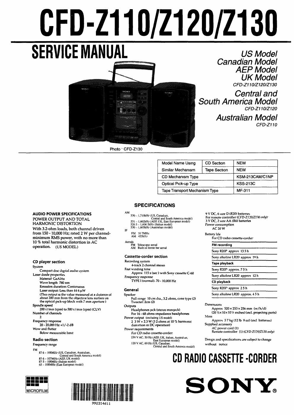
Sony cfd z 130 service manual
This is the 33 pages manual for sony cfd z 130 service manual.
Read or download the pdf for free. If you want to contribute, please upload pdfs to audioservicemanuals.wetransfer.com.
Extracted text from sony cfd z 130 service manual (Ocr-read)
Page 1
CFD- Z1_|0/Z1_20_/Z_130
if!
SERVICE MANUAL
US Model
Canadian Model
AEP Model
UK Model
CFD-Z 1 10/2120/2130
Central and
South America Model
CFDZ 1 10/2120
Australian Model
CFD
Model Name Ustng OD Section NEW
Similar Mechanism Tape Section NEW
CD Mechanism Type KSM-ZtaCAM/Cl NP
Optical Pick-up Type KSS-21SC
Tape Transport Mechanism Type MF-31 1
SPECIFICATIONS
CSSER'3$§U?E"3$$°" at
AN TAL all a an II merlca mo
HARMONIC DISTORTION 22; g1fiélé?fi3¥%§{.fif§§i§" W
With 3.2mm loads, both channel driven ,F 53 " 5" WW "W
from 150 - 10,000 Hz; rated 2 W per channel- FM 107MHL
minimum RMS power, With no more than AM 455"
ll) % total harmonic distortion in AC Mm
FM Telescopic renal
operation. AM BuilHti {emu bar unal
(US MODEL)
Cassette-(order section
Recording system
CD player section
rank 2 channel stereo
53mm Fist w riding time
Com m disc dt ml audio svslem x .
User an; rmpeni: - Approx 113 5 (sec ) With Suny cassette cw
Frequency respmlse
Material" GaAlAs TYPE l (normal). 70 - 10.0% Hz
Wave length 780 nm
Emission duration: Continuous
Laser output: Less than 4+6uw General
(This output Is the value measured at a distance of Speaker
about 200 mm from the nbiective lens surface on mu m use 10 cm dla., 3.1 ohms, cone type (2)
the optical pick-up block With 7 mm aperture ) Tweeter. 2cm (2)
Spindle speed Outputs
100 H mm (rpm) to 500 r/mln (rpm) lCLV) Headphones luck (stereo .nlnnack)
Number of channeb For 16 - 68 ohms impedance headphones
2 Power output (excluding us model)
Frequency response 2 3 w + 2.3 W (3 2 ohms at it) '3: IllnnunK
20-20.000H2 +ll-2dB
WOW and flutter
Below measurable limit
distortion in DC operation)
Power requirements
For CD radio cassette-cadet:
230an so Hz(AEP, UK, llaiiai-l Ausnraiiin.
Radio section m V AC 60 H Easslgumrcan model)
1 ( undlnn
Frequency fans? Central and South America model)
FM
87 6 - IIlSMHI (US. Canadian, Australian,
Central and Smith America model)
87 6 - IMMHL (AEP, UK model)
87 5 - IDSMHZ (lulilm model)
65 - 108MH1(Easl European model)
llllllilllll lll'l llllll
992314611
MICROFILM
llllllllll
\J V DC, 6 NZ? D (R20) batteries
Fm remote controller (C F D-ZlIU/Zl 30 mily)
3 V DC, 2 size AA (R6) batterles
Power tonsil mption
AC 20 W
Emery liti.I
For CD radio cassettemrder
FM recording
Sony RZUI appmli 13 5 II
Sony alkaline LR20 approx 19 II
Tape playback
Surly RZOP' approx. 7 5 II
Sony niknilne LRZO appmt I2 h
(D playback
Sony MOI approx 2 5 h
Suny nlknlnm LRZO npprux. i 5 [1
Dimensions
Approx 520x 253 x 156 mm (w/h/d)
(20 /:x tax 105 . inches) (incl pmltdmg parts)
Mass
Approx 5 7 kg (12 lb 902) (Ind batteries)
Supplied accessory
AC power cord u)
Remote controller (1) (CFD»lell/Z 130 only)
Design and specification: ilre subpett to change
u-lthuut noun.»
CD RADIO CASSETTE -CORDER
SONY;
Page 2
CLASS 1 LASER PRODUCT
LUOKAN I LASERIAITE
KLASS 1 LASERAPPARKF
This Compact Disc player is classrfied as a
CLASS I LASER product.
The CLASS 1 LASER PRODUCT label is
located on the rear extenor.
CAUTION
Use of controls or adjustments or performance
of procedures other than those spectfied herein
may result in hazardous radiation exposure.
MODEL IDENTIFICATION
- Model Number Label -
CFD-Z1 1 o
CFO-2120
CF D~ZI 30
SONY:
MODEL No. mm
on RADIO CASSETTE-CORDER
//////////////////////////
US. Canadianpentral & South America modal : AC 120V~60Hz
AEP. UK. Italian. Australian.East European model :AC 230V~50Hz
SAFETY-RELATED COMPONENT WARNING"
COMPONENTSIDENTIFIED BY MARK AOR 0011' ED LINEWITH
MARK AON THE SCHEMATIC DIAGRAMS AND IN THE PARTS
LIST ARE CRITICAL TO SAFE OPERATION.
REPLACE THESE COMPONENTS WITH SONY PARTS WHOSE
PART NUMBERS APPEAR AS SHOWN IN THIS MANUAL OR IN
SUPPLEMENTS PUBLISHED BY SONY.
TABLE OF CONTENTS
1. SERVICING NOTES .....
2. GENERAL
Location and Function of Controls .
3. DISASSEMBLV
3-1. Rear Cabinet Assy Removal ......................................
3-2. Power Board Removal ...............................
3-3. Main Board. Surround SW Board Removal ..
3-4. Mechanism Deck Removal .............
3-5. Cassette Holder Assy Removal .......
3-6. Control Board, Lamp Board.
CD Main Board Removal .....................................
3-7. Optical Pick-up Block CD Motor Board Removal
4. DIAL POINTER INSTALLATION ............................... 10
5. ADJUSTMENTS
5-1. Mechanical Adjustments ..
5-2. Electrical Adjustments .
6. EXPLANATION OF ICTERMINALS ......................... 18
7. DIAGRAMS
7-]. Block Diagram ...................................
7-2. Printed Wiring Boards - CD Section
7-3. Schematic Diagram - CD Section -
7-4. Schematic Diagram - Main Section - .
7-5, Printed Wiring Boards - Main Section -
8. EXPLODED VIEWS
8-1. Cabinet Section
8-2. Front Cabinet Section ..
8-3. Mechanism Deck Section -1 (MF-31 l) . 40
8-4. Mechanism Deck Section -2 (MP-Ell) . 41
8-5. CD Block Section .............................. .
8-6. Optical Pick-up Section (KSM-213CAMIC1NP) 43
8-7. Speaker Section ........................................................ 44
ELECTRICAL PARTS LIST ........................................ 45
ATTENTION AU COMPOSANT AYANT RAPPORT
A LA SECURITEI
LES COMPOSANTS IDENnFIES PAR UNE MAROUE ASUR LES
DIAGRAMMES SCHEMATIGUES ET LA LISTE DES PIECES
SON'I' CRITIQUES POUR LA SECURITE DE FONCTIONNEMENT.
NE REMPLACER CES COMPOSANTS OUE PAR DES PIECES
SONY DONT LES NUMEROS SONT DONNES DANS CE MANUEL
0U DANS LES SUPPLEMENTS PUBLIES PAR SONY.