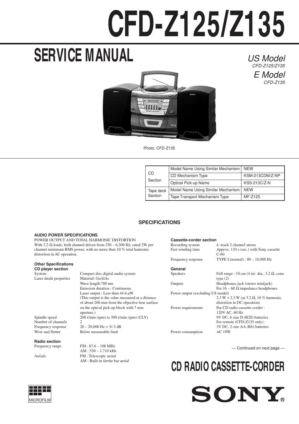
Sony cfd z 125 service manual
This is the 42 pages manual for sony cfd z 125 service manual.
Read or download the pdf for free. If you want to contribute, please upload pdfs to audioservicemanuals.wetransfer.com.
Extracted text from sony cfd z 125 service manual (Ocr-read)
Page 1
Ñ 2 Ñ Battery life For CD radio cassette-corder: FM recording Sony R20P : approx. 7 h Sony alkaline LR20 : approx. 14.5 h Tape playback Sony R20P : approx. 3.5 h Sony alkaline LR20 : approx. 8 h CD playback Sony R20P : approx. 2 h Sony alkaline LR20 : approx. 4.5 h Dimensions Approx. 622 ´ 275 ´ 230 mm (w/h/d) (24 1/2 ´ 10 7/8 ´ 9 1/8 inches) (incl. projecting parts) Mass Approx. 6.8 kg (15 lb.) (incl. batteries) Supplied accessories AC power cord (1) Remote controller (1) (CFD-Z135 only) Design and specifications are subject to chang e without notice. SAFETY-RELATED COMPONENT WARNING!! COMPONENTS IDENTIFIED BY MARK ! OR DOTTED LINE WITH MARK ! ON THE SCHEMATIC DIAGRAMS AND IN THE PARTS LIST ARE CRITICAL TO SAFE OPERATION. REPLACE THESE COMPONENTS WITH SONY PARTS WHOSE PART NUMBERS APPEAR AS SHOWN IN THIS MANUAL OR IN SUPPLEMENTS PUBLISHED BY SONY. After correcting the original service problem, perform the following safety checks before releasing the set to the customer: Check the antenna terminals, metal trim, ÒmetallizedÓ knobs, screws, and all other exposed metal parts for AC leakage. Check leakage as described below. LEAKAGE The AC leakage from any exposed metal part to earth ground and from all exposed metal parts to any exposed metal part having a return to chassis, must not exceed 0.5 mA (500 microamperes). Leakage current can be measured by any one of three methods. 1. A commercial leakage tester, such as the Simpson 229 or RCA WT-540A. Follow the manufacturersÕ instructions to use these instruments. 2. A battery-operated AC milliammeter. The Data Precision 245 digital multimeter is suitable for this job. 3. Measuring the voltage drop across a resistor by means of a VOM or battery-operated AC voltmeter. The ÒlimitÓ indication is 0.75 V, so analog meters must have an accurate low-voltage scale. The Simpson 250 and Sanwa SH-63Trd are examples of a passive VOM that is suitable. Nearly all battery operated digital multimeters that have a 2V AC range are suitable. (See Fig. A) SAFETY CHECK-OUT To Exposed Metal Parts on Set 0.15 µF 1.5 k ½ AC Voltmeter (0.75 V) Earth Ground Fig. A. Using an AC voltmeter to check AC leakage. CAUTION Use of controls or adjustments or performance of procedures other than those specified herein may result in hazardous radiation exposure. TABLE OF CONTENTS 1. SERVICE NOTES ááááááááááááááááááááááááááááááááááááááááááááááááááá\ ááááááááá 3 2. GENERAL ááááááááááááááááááááááááááááááááááááááááááááááááááá\ ááááááááááááááááááááááá 4 3. DISASSEMBLY 3-1. Rear Cabinet ááááááááááááááááááááááááááááááááááááááááááááááááááá\ áááááááááááááááááááá 9 3-2. CD Block ááááááááááááááááááááááááááááááááááááááááááááááááááá\ ááááááááááááááááááááááá 10 3-3. Main Board, SP Terminal Board áááááááááááááááááááááááááááááááááááááá 10 3-4. CD Decoder Board, Lamp Board ááááááááááááááááááááááááááááááááááááá 11 3-5. Optical Pick-up Section (KSM-213CDM/Z-NP) ááááááááááááá 11 3-6. Optical Pick-up (KSS-213C/Z-N) áááááááááááááááááááááááááááááááááááá 12 3-7. Motor Board, Sled Motor (M702) áááááááááááááááááááááááááááááááááááá 12 3-8. Front Board, Sensor Board ááááááááááááááááááááááááááááááááááááááááááááááá 13 3-9. Mechanism Deck (MF-Z125) ááááááááááááááááááááááááááááááááááááááááááá 13 3-10. Belt, Capstan/Reel Motor (M601) áááááááááááááááááááááááááááááááááááá 14 3-11. Cassette Door ááááááááááááááááááááááááááááááááááááááááááááááááááá\ áááááááááááááááá 14 4. DIAL POINTER SETTING áááááááááááááááááááááááááááááááááááááááááá 15 5. ADJUSTMENTS 5-1. Mechanical Adjustment ááááááááááááááááááááááááááááááááááááááááááááááááááá\ á 16 5-2. Electrical Adjustment Tape Deck Section ááááááááááááááááááááááááááááááááááááááááááááááááááá\ ááááááááá 16 Tuner Section ááááááááááááááááááááááááááááááááááááááááááááááááááá\ ááááááááááááááááá 18 CD Section ááááááááááááááááááááááááááááááááááááááááááááááááááá\ áááááááááááááááááááá 20 6. DIAGRAMS 6-1. Circuit Boards Location ááááááááááááááááááááááááááááááááááááááááááááááááááá\ 23 6-2. Block Diagram ááááááááááááááááááááááááááááááááááááááááááááááááááá\ áááááááááááááá 24 6-3. Printed Wiring Board ÑCD Section Ñ ááááááááááááááááááááááááááá 29 6-4. Schematic Diagram Ñ CD Section Ñ ááááááááááááááááááááááááááááá 32 6-5. Schematic Diagram Ñ Main Section Ñ ááááááááááááááááááááááááá 35 6-6. Printed Wiring Board ÑMain Section Ñ áááááááááááááááááááááááá 39 6-7. Printed Wiring Board ÑFront Section Ñ áááááááááááááááááááááááá 43 6-8. Schematic Diagram ÑFront Section Ñ ááááááááááááááááááááááááááá 45 6-9. IC Pin Function Description ááááááááááááááááááááááááááááááááááááááááááááá 47 7. EXPLODED VIEWS 7-1. Back Cabinet Section ááááááááááááááááááááááááááááááááááááááááááááááááááá\ áááá 49 7-2. Front Panel Section ááááááááááááááááááááááááááááááááááááááááááááááááááá\ ááááááá 50 7-3. CD Block Section ááááááááááááááááááááááááááááááááááááááááááááááááááá\ áááááááááá 51 7-4. Optical Pick-up Section (KSM-213CDM/Z-NP) ááááááááááááá 52 7-5. Mechanism Deck Section-1 áááááááááááááááááááááááááááááááááááááááááááááá 53 7-6. Mechanism Deck Section-2 áááááááááááááááááááááááááááááááááááááááááááááá 54 7-7. Speaker Section ááááááááááááááááááááááááááááááááááááááááááááááááááá\ ááááááááááááá 55 8. ELECTRICAL PARTS LIST ááááááááááááááááááááááááááááááááááááááá 56
Page 2
Ñ 3 Ñ SECTION 1 SERVICE NOTES NOTES ON HANDLING THE OPTICAL PICK-UP BLOCK OR BASE UNIT The laser diode in the optical pick-up block may suffer electrostatic breakdown because of the potential difference generated by the charged electrostatic load, etc. on clothing and the human body. During repair, pay attention to electrostatic breakdown and also use the procedure in the printed matter which is included in the repair parts. The flexible board is easily damaged and should be handled with care. NOTES ON LASER DIODE EMISSION CHECK The laser beam on this model is concentrated so as to be focused on the disc reflective surface by the objective lens in the optical pick- up block. Therefore, when checking the laser diode emission, observe from more than 30 cm away from the objective lens. CHUCK PLATE JIG ON REPAIRING On repairing CD section, playing a disc without the CD lid, use Chuck Plate Jig. · Code number of Chuck Plate Jig : X-4918-255-1 LASER DIODE AND FOCUS SEARCH OPERATION CHECK 1. Turn POWER switch on with no disc inserted and make Function switch to CD position. 2. Open the lid for CD. 3. Turn on S702 as following figure. 4. Press the ß button. 5. Confirm the laser diode emission while observing the objecting lens. When there is no emission, Auto Power Control circuit or optical pick-up is broken. Objective lens moves up and down three times for the focus search. HOW TO CHANGE THE FM CERAMIC FILTERS This model uses the two ceramic filters of CF1 and CF4. You must use the same type of color marked ceramic filters in order to meet same specifications. Therefore, the ceramic filter must change two pieces together since itÕs supply two pieces in one package as a spare parts. Mark 1 Mark 2Center frequency red Ñ 10.70MHz blue Ñ 10.67MHz orange Ñ 10.73MHz black Ñ 10.64MHz white Ñ 10.76MHz white white 10.75MHz yellow Ñ 10.79MHz mark 1 mark 2 CF1,4 S702