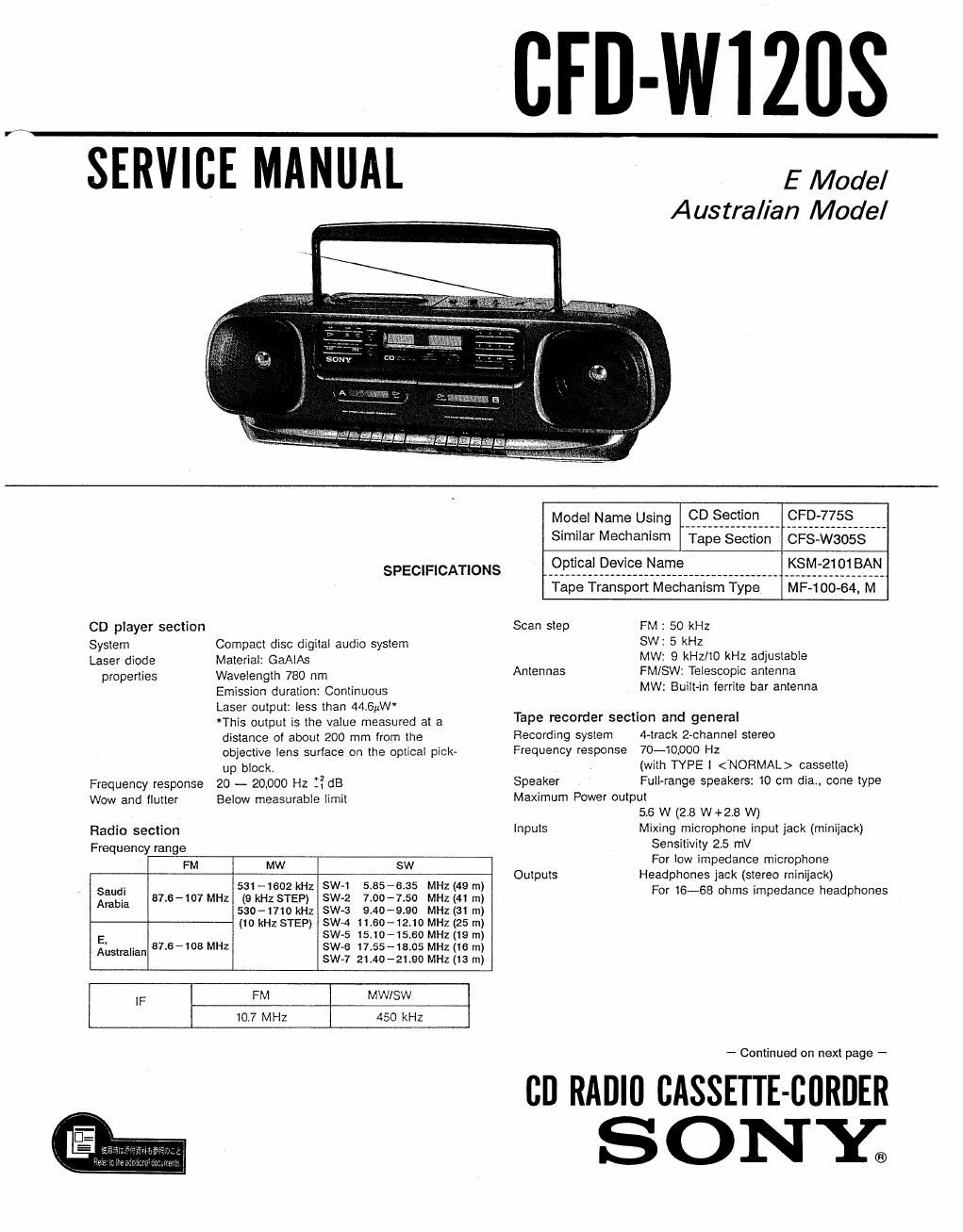
Sony cfd w 120 s service manual
This is the 51 pages manual for sony cfd w 120 s service manual.
Read or download the pdf for free. If you want to contribute, please upload pdfs to audioservicemanuals.wetransfer.com.
Extracted text from sony cfd w 120 s service manual (Ocr-read)
Page 2
CFD-W1ZOS
Power requirements
Australian model
240 V AC, 50 HZ
Emodel 110-120V,220-240VAC
adjustable, 50/60 Hz
DC9 V, 6 R20 (size D) batteries
Power consumption
A025 W
Battery life (hours)
FM recording Playback CD playing
Sony SUM-1 (NS) aprrox. 7.5 approx. 55 approx. 25
Sony Alkaline AM1 (N) approx. 17 approx. 11 approx. 4.5
For tuner memory: Approx. 1 year
Dimensions 640 x 205 x 224 mm (w/h/d)
(251/4 x 81/3 x 87/8 inches)
incl, projecting parts and controls
Weight Approx. 5.4 kg. incl. batteries
(Approx. 11 lb 14 oz).
Supplied accessories AC power cord (1)
Design andspecitications subject to change without notice.
Note
This appliance coniorms with EEC Directive 87/308/EEC regarding
interference suppression.
MODEL IDENTIFICATION
- Model Number Label -
Australian model:
E model :
AC: 240 V ~50Hz 25 W
A02110~120 V, 220-240 V~
50/60 Hz 25W
MODEL No. CFD-W1205
CD RADIO CASSETTE-CORDER
V/////////////////////////////////////////////////¢
DC: 9v 2: FLASHLIGHT BATTERY
R20 SIZE D x e on EQUIVALENT
W
E model: Carved on rear cabinet
Saudi Arabia model: 3-371-893-01
Australian model: 3-371-894-01
TAB LE OF CONTENTS
Section Title Page
Specifications .................................. 1
1. SERVICING NOTES
2. GENERAL
Parts Identification --------------------- 4
3. DISASSEMBLY ......................... 5
4. MECHANICAL ADJUSTMENTS
Torque Measurement ~~~~~~~~~~~~~~~~~~~~ 7
Tape Tension Measurement ~~~~~~~~~~~~~~~~ 7
5. ELECTRICAL ADJUSTMENTS
S~1. Tape Recorder Section 7
52. Tuner Section ~~~~~~~~ 8
5.3. CD Section .............................. 10
6. DIAGRAMS
6-1, 1C Port Function Description ~~~~~~~~~~~~~~~ 14
6-2. Tuner, Display Section Block Diagram ----- 16
63. CD Section Block Diagram ~~~~~~~~~~~~~~~~~ 17
6-4. Audio, Power Supply Section Block Diagram ~ 19
6-5. Tuner, Display Section Printed Wiring Boards
and Schematic Diagram ~~~~~~~~~~~~~~~~~~ 21
66. Tape, CD, Power Supply Section
Printed Wiring Boards - -
6~7. .Audio, Power Supply Section
Schematic Diagram ~~~~~~~~~~~~~~~~~~~~ 31
6-8. CD Section Schematic Diagram ~~~~~ - 36
7. EXPLODED VIEWS ~~~~~~~~~~~~~~~~~~~ 41
8. ELECTRICAL PARTS LIST ~~~~~~~~~~~ 47
SAFETY-RELATED COMPONENT WARNINGI!
COMPONENTS IDENTIFIED BY MARK A 0R DOTTED
LINE WITH MARK A ON THE SCHEMATIC DIAGRAMS
AND IN THE PARTS LIST ARE CRITICAL T0 SAFE
OPERATION. REPLACE THESE COMPONENTS WITH
SONY PARTS WHOSE PART NUMBERS APPEAR AS
SHOWN IN THIS MANUAL OR IN SUPPLEMENTS PUB-
LISHED BY SONY.