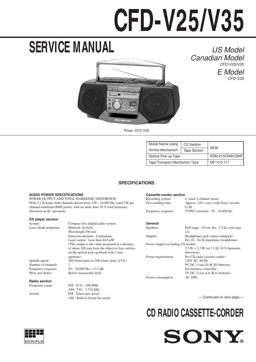
Sony cfd v 35 service manual
This is the 36 pages manual for sony cfd v 35 service manual.
Read or download the pdf for free. If you want to contribute, please upload pdfs to audioservicemanuals.wetransfer.com.
Extracted text from sony cfd v 35 service manual (Ocr-read)
Page 1
Ñ 2 Ñ Battery life For CD radio cassette-corder: FM recording Sony R20P : approx. 13.5 h Sony alkaline LR20 : approx. 19 h Tape playback Sony R20P : approx. 7.5 h Sony alkaline LR20 : approx. 15 h CD playback Sony R20P : approx. 2.5 h Sony alkaline LR20 : approx. 6 h Dimensions Approx. 425 ´ 160 ´ 246 mm (w/h/d) (16 3/4 ´ 6 3/8 ´ 9 3/4 inches) (incl. projecting parts) Mass Approx. 4.2 kg (9 lb. 4 oz) (incl. batteries) Supplied accessories AC power cord (1) Remote controller (1) Design and specifications are subject to chang e without notice. Optional accessories Sony MDR headphones series TABLE OF CONTENTS 1. SERVICE NOTES ááááááááááááááááááááááááááááááááááááááááááááááááááá\ ááááááááá 3 2. GENERAL ááááááááááááááááááááááááááááááááááááááááááááááááááá\ ááááááááááááááááááááááá 4 3. DISASSEMBLY 3-1. Front Cabinet, Control (1) Board, Control (2) Board, Headphone Board ááááááááááááááááááááááááááááááááááááááááááááááááááá\ áááááááááááá 9 3-2. Upper Cabinet ááááááááááááááááááááááááááááááááááááááááááááááááááá\ áááááááááááááááááá 9 3-3. Optical Pick-up ááááááááááááááááááááááááááááááááááááááááááááááááááá\ áááááááááááááá 10 3-4. Mechanism Deck, Rec sw Board, Main Board, Power Board, Primary Board, Batt Board áááááááááááááááááááááááá 10 4. ADJUSTMENTS 4-1. Mechanical Adjustment ááááááááááááááááááááááááááááááááááááááááááááááááááá\ á 11 4-2. Electrical Adjustment ááááááááááááááááááááááááááááááááááááááááááááááááááá\ áááá 11 4-3. Tuner Section ááááááááááááááááááááááááááááááááááááááááááááááááááá\ ááááááááááááááááá 12 4-4. Reference ááááááááááááááááááááááááááááááááááááááááááááááááááá\ ááááááááááááááááááááááá 15 5. DIAGRAMS 5-1. Circuit Board Location ááááááááááááááááááááááááááááááááááááááááááááááááááá\ áá 17 5-2. IC Pin Function ááááááááááááááááááááááááááááááááááááááááááááááááááá\ ááááááááááááá 18 5-3. Block Diagram ááááááááááááááááááááááááááááááááááááááááááááááááááá\ áááááááááááááá 20 5-4. Printed Wiring Board ááááááááááááááááááááááááááááááááááááááááááááááááááá\ ááááá 23 5-5. Schematic Diagram Ð Tuner/System Section Ð áááááááááááááááá 27 5-6. Schematic Diagram Ð Power Section Ð áááááááááááááááááááááááááááá 31 5-7. Schematic Diagram Ð CD Section Ð ááááááááááááááááááááááááááááááááá 35 5-8. IC Block Diagrams ááááááááááááááááááááááááááááááááááááááááááááááááááá\ áááááááá 38 6. EXPLODED VIEWS 6-1. Front Cabinet Section ááááááááááááááááááááááááááááááááááááááááááááááááááá\ áááá 39 6-2. Upper Cabinet Section ááááááááááááááááááááááááááááááááááááááááááááááááááá\ ááá 40 6-3. Rear Cabinet Section ááááááááááááááááááááááááááááááááááááááááááááááááááá\ ááááá 41 6-4. Mechanism Deck Setion (1) (MF-V10-117) áááááááááááááááááááá 42 6-5. Mechanism Deck Setion (2) (MF-V10-117) áááááááááááááááááááá 43 6-6. Optical Pick-up Section (KSM-213CDM/C2NP) áááááááááááá 44 7. ELECTRICAL PARTS LIST ááááááááááááááááááááááááááááááááááááááá 45 SAFETY-RELATED COMPONENT WARNING!! COMPONENTS IDENTIFIED BY MARK ! OR DOTTED LINE WITH MARK ! ON THE SCHEMATIC DIAGRAMS AND IN THE PARTS LIST ARE CRITICAL TO SAFE OPERATION. REPLACE THESE COMPONENTS WITH SONY PARTS WHOSE PART NUMBERS APPEAR AS SHOWN IN THIS MANUAL OR IN SUPPLEMENTS PUBLISHED BY SONY. ATTENTION AU COMPOSANT AYANT RAPPORT Ë LA SƒCURITƒ! LES COMPOSANTS IDENTIFƒS PAR UNE MARQUE ! SUR LES DIAGRAMMES SCHƒMATIQUES ET LA LISTE DES PIéCES SONT CRITIQUES POUR LA SƒCURITƒ DE FONCTIONNEMENT. NE REMPLACER CES COMPOSANTS QUE PAR DES PIéSES SONY DONT LES NUMƒROS SONT DONNƒS DANS CE MANUEL OU DANS LES SUPPƒMENTS PUBLIƒS PAR SONY. After correcting the original service problem, perform the following safety checks before releasing the set to the customer: Check the antenna terminals, metal trim, ÒmetallizedÓ knobs, screws, and all other exposed metal parts for AC leakage. Check leakage as described below. LEAKAGE The AC leakage from any exposed metal part to earth ground and from all exposed metal parts to any exposed metal part having a return to chassis, must not exceed 0.5 mA (500 microamperes). Leakage current can be measured by any one of three methods. 1. A commercial leakage tester, such as the Simpson 229 or RCA WT-540A. Follow the manufacturersÕ instructions to use these instruments. 2. A battery-operated AC milliammeter. The Data Precision 245 digital multimeter is suitable for this job. 3. Measuring the voltage drop across a resistor by means of a VOM or battery-operated AC voltmeter. The ÒlimitÓ indication is 0.75 V, so analog meters must have an accurate low-voltage scale. The Simpson 250 and Sanwa SH-63Trd are examples of a passive VOM that is suitable. Nearly all battery operated digital multimeters that have a 2V AC range are suitable. (See Fig. A) SAFETY CHECK-OUT To Exposed Metal Parts on Set 0.15 µF 1.5 k ½ AC Voltmeter (0.75 V) Earth Ground Fig. A. Using an AC voltmeter to check AC leakage.