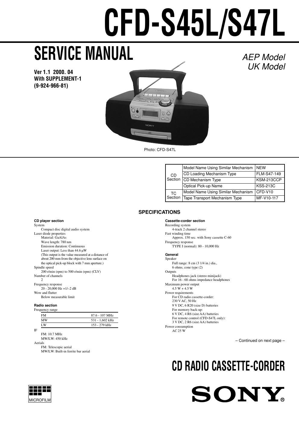
Sony cfd s 47 l service manual
This is the 47 pages manual for sony cfd s 47 l service manual.
Read or download the pdf for free. If you want to contribute, please upload pdfs to audioservicemanuals.wetransfer.com.
Extracted text from sony cfd s 47 l service manual (Ocr-read)
Page 2
– 3 – TABLE OF CONTENTS 1. GENERAL Playing a CD ........................................................................... 4 Listening to the radio ............................................................... 4 Playing a tape .......................................................................... 5 Recording on a tape ................................................................. 5 2. DISASSEMBLY 2-1. Cabinet (Front) Assy ........................................................... 6 2-2. Power Board ........................................................................ 6 2-3. Cabinet (Upper) Assy .......................................................... 7 2-4. CD Mechanism Block ......................................................... 7 2-5. Tuner Board ......................................................................... 8 2-6. SW (L) Board, SW (R) Board ............................................. 8 2-7. Main Board ......................................................................... 9 2-8. SW (Top) Board, Record/Playback Switch Board, Headphone Board ................................................................ 9 2-9. Cassette Mechanism Block ............................................... 10 2-10. Chuck Plate Assy .............................................................. 10 2-11. Tray ................................................................................... 11 2-12. Loading Board ................................................................... 11 2-13. CD Board .......................................................................... 12 2-14. CD Mechanism Block ....................................................... 12 3. MECHANICAL ADJUSTMENTS ............................... 13 4. ELECTRICAL ADJUSTMENTS Tape Section .......................................................................... 13 Tuner Section ......................................................................... 14 CD Section ............................................................................ 15 5. DIAGRAMS 5-1. IC Pin Description ............................................................. 16 5-2. Circuit Boards Location .................................................... 18 5-3. Block Diagram – CD Section – ......................................... 19 5-4. Block Diagram – Main Section – ...................................... 21 5-5. Printed Wiring Board – Tuner Section – ........................... 24 5-6. Schematic Diagram – Tuner Section – .............................. 25 5-7. Printed Wiring Boards – CD Section – ............................. 27 5-8. Schematic Diagram – CD Section – .................................. 29 5-9. Printed Wiring Boards – Main Section – .......................... 32 5-10. Schematic Diagram – Main Section (1/2) – ...................... 35 5-11. Schematic Diagram – Main Section (2/2) – ...................... 38 6. EXPLODED VIEWS 6-1. Cabinet (Front) Section ..................................................... 44 6-2. Cabinet (Upper) Section .................................................... 45 6-3. CD Chassis Section ........................................................... 46 6-4. Tape Mechanism Deck Section-1 ...................................... 47 6-5. Tape Mechanism Deck Section-2 ...................................... 48 6-6. Optical Pick-up Section .................................................... 49 7. ELECTRICAL PARTS LIST ......................................... 50