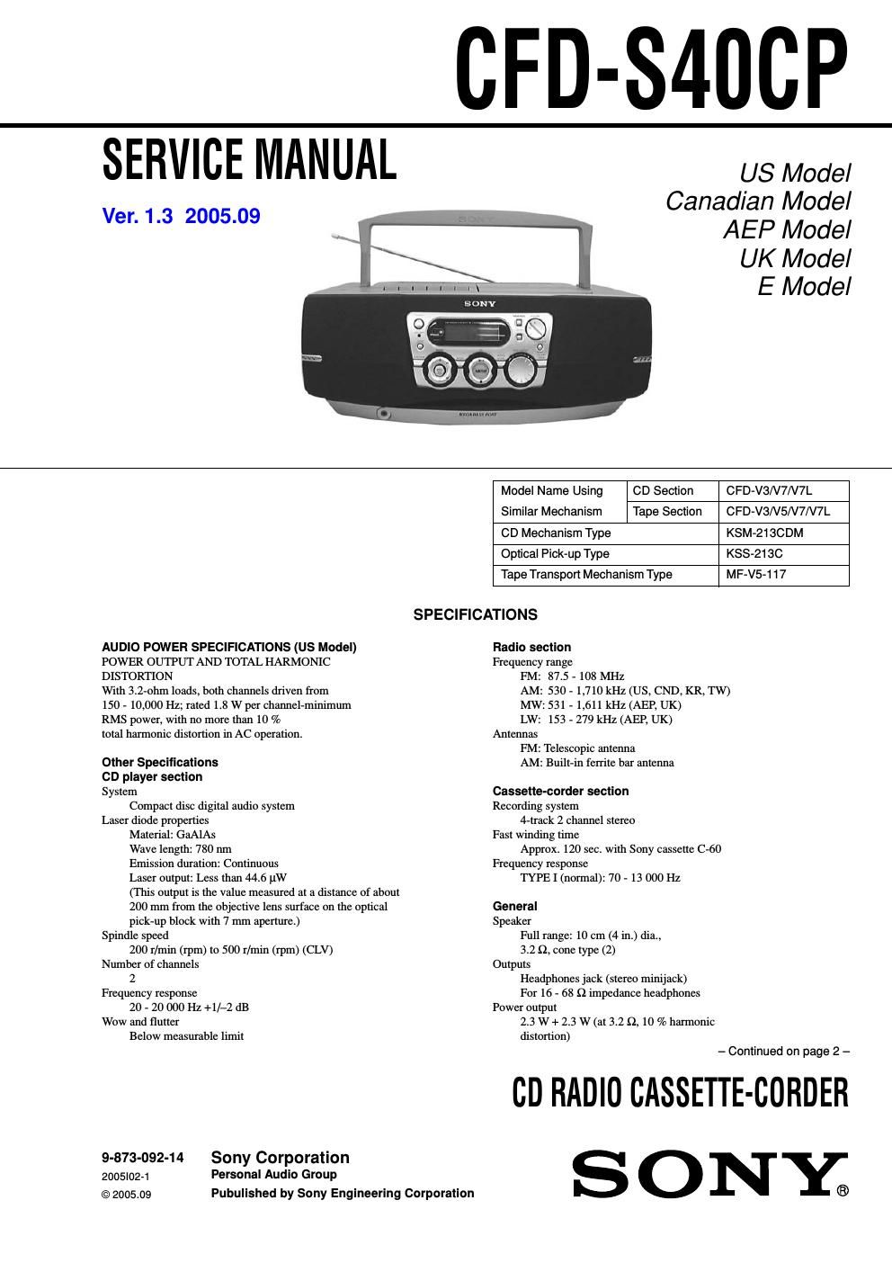
Sony cfd s 40 cp service manual
This is the 58 pages manual for sony cfd s 40 cp service manual.
Read or download the pdf for free. If you want to contribute, please upload pdfs to audioservicemanuals.wetransfer.com.
Extracted text from sony cfd s 40 cp service manual (Ocr-read)
Page 1
CFD-S4UCP
SERVICE MANUAL
Ver. 1.3 2005.09
US Model
Canadian Model
AEP Model
UK Model
E Model
C D Sectio n
Tape Section
CFD-V3/V7/V7L
CFD-V3N5/V7/V7L
Model Name Using
Similar Mechanism
CD Mechanism Type KSM-21SCDM
Optical Pick-up Type KSS-2130
Tape Transport Mechanism Type MF-V5-1 17
SPECIFICATIONS
AUDIO POWER SPECIFICATIONS (US Model)
POWER OUTPUT AND TOTAL HARMONIC
DISTORTION
With 3.2-ohm loads, both channels driven from
150 - 10,000 Hz; rated 1.8 W per channel-minimum
RMS power, with no more than 10 %
total harmonic distortion in AC operation.
Other Specifications
CD player section
System
Compact disc digital audio system
Laser diode properties
Material: GaAlAs
Wave length: 780 nm
Emission duration: Continuous
Laser output: Less than 44.6 11W
(This output is the value measured at a distance of about
200 mm from the objective lens surface on the optical
pick-up block with 7 mm aperture.)
Spindle speed
200 r/min (rpm) to 500 r/min (rpm) (CLV)
Number of channels
2
Frequency response
20 - 20 000 Hz +l/-2 dB
Wow and flutter
Below measurable limit
9-873-092-14 Sony Corporation
2005|0271 Personal Audio Group
©2005.09 Pubulished by Sony Engineering Corporation
Radio section
Frequency range
FM: 87.5 - 108 MHz
AM: 530 - 1,710 kHz (US, CND, KR, TW)
MW: 531 - 1,611 kHz (AEP, UK)
LW: 153 - 279 kHz (AEP, UK)
Antennas
FM: Telescopic antenna
AM: Built-in ferrite bar antenna
Cassette-corder section
Recording system
4-track 2 channel stereo
Fast winding time
Approx. 120 sec. with Sony Cassette C-60
Frequency response
TYPE 1 (normal): 70 - 13 000 Hz
General
Speaker
Full range: 10 cm (4 in.) dia.,
3.2 Q, cone type (2)
Outputs
Headphones jack (stereo minijack)
For 16 - 68 Q impedance headphones
Power output
2.3 W + 2.3 W (at 3.2 Q, 10 % harmonic
distortion)
- Continued on page 2 -
co RADIO CASSETTE-CORDER
S 0 NY.)
Page 2
CFD-S40CP
Ver1.1 2001.07
Power requirements
For CD radio cassette-corder:
120 V AC, 60 Hz (US, CND, TW)
230 V AC, 50 Hz (AEP, UK, KR)
9 V DC, 6 size D (R20) batteries
For memory back-up:
6 V DC, 4 size AA (R6) batteries
For remote control:
3 V DC, 2 size AA (R6) batteries
Power consumption
AC 20 W
Battery life
For CD radio cassette-corder:
FM recording
Sony RZOP: approx. 15 h
Sony alk e LR20: approx. 40 h
Tape playback
Sony RZOP: approx. 10 h
Sony alkaline LR20: approx. 25 h
CD playback
Sony RZOP: approx. 1.5 h
Sony alkaline LR20: approx. 6 h
Dimensions
Approx. 420 X 161 X 266 mm (w/h/d)
(16 5/8 X 6 3/8 X 101/2 inches) (incli projecting parts)
Mass
Approx. 4.6 kg (10 lb. 2 oz) (incl. batteries)
Supplied accessories
AC power cord (1)
Remote control (1)
Design and specifications are subject to change without
notice.
Information
For customers in Europe
CLASS 1 LASER PRODUCT
LUOKAN 1 LASERLAITE
KLASS 1 LASERAPPARAT
This Compact Disc player is classified as a CLASS 1 LASER
product
The CLASS 1 LASER PRODUCT label is located at the bottom
of the playeri
CAUTION
Use of controls or adjustments or performance
of procedures other than those specified herein
may result in hazardous radiation exposure
SAFETY-RELATED COMPONENT WARNING !!
COMPONENTS IDENTIFIED BY MARK A OR DOTTED LINEWITH
MARK A ON THE SCHEMATIC DIAGRAMS AND IN THE PARTS
LIST ARE CRITICAL TO SAFE OPERATION.
REPLACE THESE COMPONENTS WITH SONY PARTS WHOSE
PART NUMBERS APPEAR AS SHOWN IN THIS MANUAL OR IN
SUPPLEMENTS PUBLISHED BY SONY.
ATTENTION AU COMPOSANT AYANT RAPPORT
A LA SECURITE!!
LES COMPOSANTS IDENTIFIES PAR UNE MAROUE A SUR
LES DIAGRAMMES SCHEMATIQUES ET LA LISTE DES
PIECES SONT CRITIQUES POUR LA SECURITE DE
FONCTIONNEMENT. NE REMPLACER CES COMPOSANTS
OUE PAR DES PIECES SONY DONT LES NUMEROS SONT
DONNES DANS CE MANUEL OU DANS LES SUPPLEMENTS
PUBLIES PAR SONY.
2
TABLE OF CONTENTS
Specifications ............................................................................... 1
1.
2.
SERVICING NOTES ...................................................... 3
GENERAL
Location and Function of Controls ....................................... 4
DISASSEMBLY
3-11
3-21
3-31
3-41
3-51
3-61
3-71
3-81
3-91
3-10.
3-11.
Cabinet (Front) ASSY, Cabinet (Rear) .
Control Board
Headphone Board
Cabinet (Upper) ASSY ........
LCD Board (with Lamp Board
Main Board
CD Board ..
Optical Pick-up Block, Mechan 'm Deck,
CD motor Board, TC Board ....................................... ll
M321 (Capstan/Reel Motor), Belt,
HRP301 Head, Magnetic (Record/Playback),
HE301 Head (Erase) .................................................. 11
Power ASSY, Battery Board,
Battery Common Board
Tuner Board ..
000000094!
ADJUSTMENTS
4-11
4-21
Mechanical Adjustments
Electrical Adjustments ..
DIAGRAMS
5-11
5-21
5-31
5-41
5-51
5-61
5-71
5-81
5-10,
5-11.
5-12.
5-13,
5-14.
5-15.
5-16.
5-17,
5-18.
Explanation of IC Terminals
Block Diagram 4 Tuner/TC Section 4
Block Diagram 4 Main Section 4
Block Diagram 4 CD Section - ..
Printed Wiring Board - TC Section 4
Schematic Diagram 4 TC Section 4 ..
Printed Wiring Board
4 Tuner Section (US, Canadian, KR, TW Model) 4.. 24
Schematic Diagram
4 Tuner Section (US. Canadian, KR, TW Model) 4.. 25
Printed Wiring Board
4 Tuner Section (AEP, UK Model) 4
Schematic Diagram
4 Tuner Section (AEP, UK Model) 4 ......................... 27
Printed Wiring Board 4 CD Section 4 ..
Schematic Diagram 4 CD Section (1/2) 4
Schematic Diagram 4 CD Section (2/2) -
Schematic Diagram 4 Main Section (1/2) 4
Schematic Diagram 4 Main Section (2/2) 4
Printed Wiring Board 4 Main Section 4 .. ,
Printed Wiring Board - Power Supply Section 4 . 34
Schematic Diagram 4 Power Supply Section 4 34
EXPLODED VIEWS
6-11
6-21
6-31
6-41
6-51
6-61
Front Cabinet Section ................................................ 40
Rear Cabinet Section ,
Upper Cabinet Section
Mechanism Deck Section (1) ,
Mechanism Deck Section (2) ,
CD Block Section ................
.42
.43
.44
ELECTRICAL PARTS LIST 46