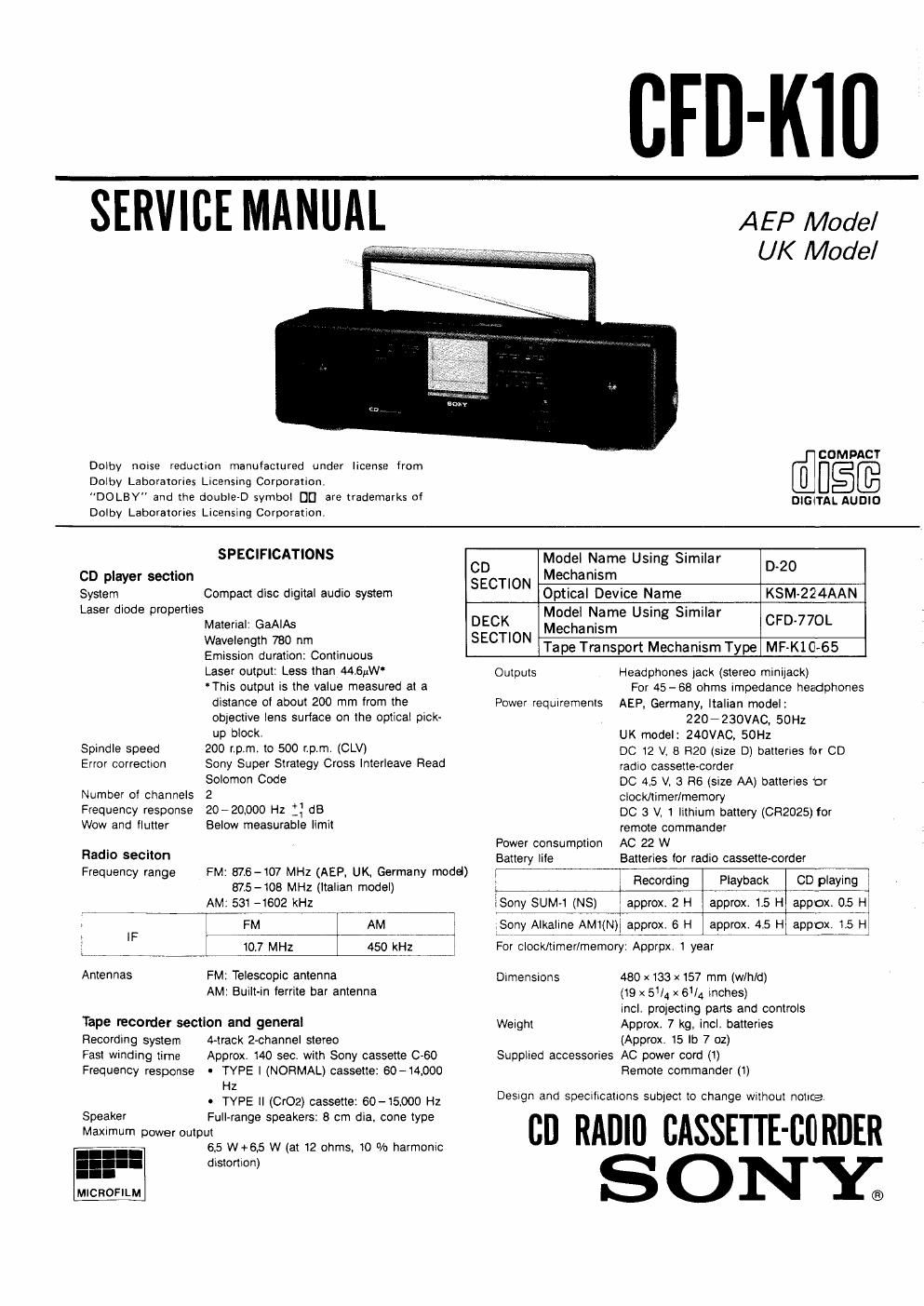
Sony cfd k 10 service manual
This is the 87 pages manual for sony cfd k 10 service manual.
Read or download the pdf for free. If you want to contribute, please upload pdfs to audioservicemanuals.wetransfer.com.
Extracted text from sony cfd k 10 service manual (Ocr-read)
Page 2
CFD-KlO
Section Title Page
1.
0 Parts Identification . . . .
TABLE OF CONTENTS
GENERAL
0 Power Source .............................. 6
OSetting the Clock . . . .
0 Playing Discs . , . .
O Adjusting Sound. . ......................... 9
0 Various disc Playing Modes ....................... 10
0 Listening to Radio Programs ...................... 12
0 Playing Back Tapes .............................. 14
0 Recording CD Sound .............................. 15
0 Automatic Editing on the CD for Recording by
Specifying the Tape Length ........................ 16
ORecording Radio Sound ............................ 17
0 Using the Built-in Timer ..... . .................... 18
2. MECHANICAL OPERATION
2-1. Operation of the cam gear ...................... 21
2-2 FWD mode .................................... 21
2-3. REV mode ........ .22
2-4. FF (REW) mode . . .23
25. FWD AMS mode ............ 23
2-6. REV AMS (REW/FF) mode ..................... 23
3. PIN DESCRIPTION
3-1. Pin Description .................................. Z4
4. DISASSEMBLY
41. Cabinet (front) Assy ............................ 27
4-2. Speaker .......................... 27
Mi Control Board iiiiiiii . . .28
4-4 Cabinet (upper) Assy - i . . .28
45. MD Block Assy ...... .29
4-6. Audio»CD Board ............ 29
4-7. Cabinet (rear) Assy .......... 30
4-8, Power Transformer . . .30
4»9. VOL Assy, Driver Board .i . i ................ 30
5. MECHANICAL ADJUSTMENTS
Deck Section ...................................... 31
6. ELECTRICAL ADJUSTMENTS
Deck SectiOn .......... 32
Tuner Section . . .35
CD Section ...................... 36
7. DIAGRAMS
7-1. Circuit Boards Location ........................ 40
7-2 Printed Wiring Boards 7 Tuner Section 7 ........ 41
7-3. Schematic Diagram 7 Tuner Section 7 .......... 42
7-4, Printed Wiring Boards - Audio/CD Section 7 . . . 446
7-5. Schematic Diagram 7 Audio/CD Section 7 ...... 51
7-6. Schematic Diagram 7 System Control/
Display Section - .............................. 55
7-7. Printed Wiring Boards - System Control/
Display/ Driver/ Deck Section 7 .................. 59
7»8. Schematic Diagram 7 Driver/Deck Section 7 . , . .64
7-9, Printed Wiring Boards 7 Volume/
7-10. Schematic Diagram 7 Volume/Power Section 7 .
POWer Section 7 ........................... .67
.69
Section Title Page
711, Semiconductor Lead Layouts .................... 71
8. EXPLODED VIEWS
8»1. Cabinet Section
8-2. Cabinet (upper) Assembly Section . .
8-3. Cabinet (rear) Assembly Section 4 . . .
84. Cabinet (center) Assembly Section .
8-5. CD Mechanism Block Section .....
8-6i Cassette MD Block Section ...................... 84
9. ELECTRICAL PARTS LIST ...................... 85
MODEL IDENTIFICATION
-Model Number Label-
SONYu MODEL N0. CFD-Klo
CD RADIO CASSETTE-CORDER
AEP, Germany, ltalian model: AC: 220-230V~50Hz 22W
UK model: AC: 240V~50Hz 22W
For AEP model
cussu user: PRODUCT classified as a CLASS 1
LUOKAN I LASERLAITE LASER product.
Kussn msmpnmr The CLASS 1 LASER
on the rear exterior
SAFETY-RELATED COMPONENT WARNING
COMPONENTS IDENTIFIED BY MARK A OR DOTTED
LINE WITH MARK A ON THE SCHEMATIC DIAGRAMS
AND IN THE PARTS LIST ARE CRITICAL TO SAFE
OPERATION. REPLACE THESE COMPONENTS WITH
SONV PARTS WHOSE PART NUMBERS APPEAR AS
SHOWN IN THIS MANUAL OR IN SUPPLEMENTS PUB-
LISHED BV SONY.
......... 79
......... 80
........... Sl
iiiiiiiiiiiii 83
This Compact Disc player is
PRODUCT label is located