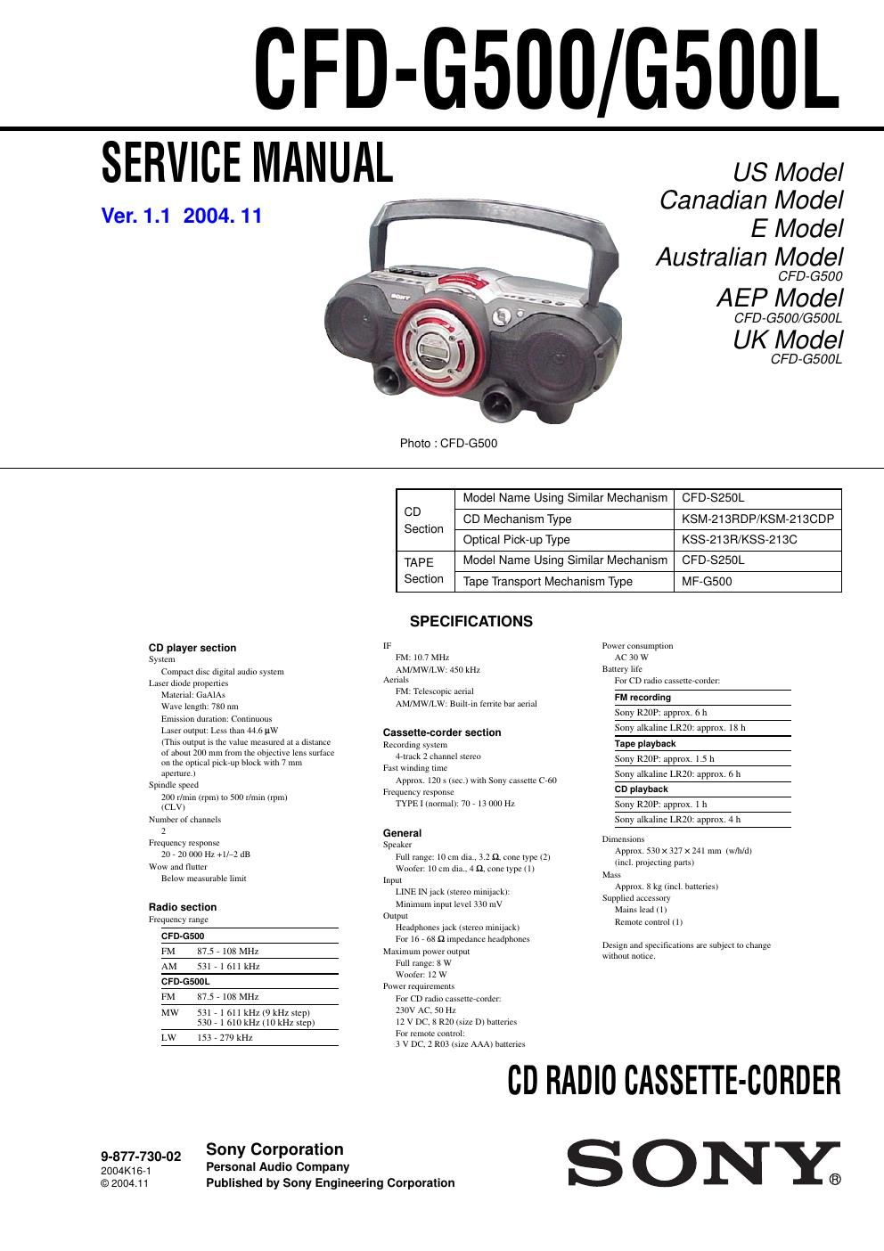
Sony cfd g 500 service manual
This is the 56 pages manual for sony cfd g 500 service manual.
Read or download the pdf for free. If you want to contribute, please upload pdfs to audioservicemanuals.wetransfer.com.
Extracted text from sony cfd g 500 service manual (Ocr-read)
Page 2
CFD-G500/G500L
Notes on chip component replacement
O Never reuse a disconnected chip component.
O Notice that the minus side of a tantalum capacitor may be
damaged by heat.
Flexible Circuit Board Repairing
O Keep the temperature of soldering iron around 270°C during
repairing.
O Do not touch the soldering iron on the same conductor of the
circuit board (within 3 times).
O Be careful not to apply force on the conductor when soldering
or unsoldering.
SAFETY-RELATED COMPONENT WARNING I!
COMPONENTS IDENTIFIED BY MARKA OR DOTTED LINEWITH
MARK A ON THE SCHEMATIC DIAGRAMS AND IN THE PARTS
LIST ARE CRITICAL TO SAFE OPERATION. REPLACE THESE
COMPONENTS WITH SONY PARTS WHOSE PART NUMBERS
APPEAR AS SHOWN IN THIS MANUAL OR IN SUPPLEMENTS
PUBLISHED BY SONY.
ATTENTION Au COMPOSANT AYANT RAPPORT
A LA SECURITE!
LES COMPOSANTS IDENTIFES PAR UNE MARQUE A sun LES
DIAGRAMMES SCHEMATIQUES ET LA LISTE DES PIECES SONT
CRITIQUES POUR LA SECURITE DE FONCTIONNEMENT. NE
REMPLACER CES COMPOSANTS QUE PAR DES PIESES SONY
DONT LES NUMEROS SONT DONNES DANS CE MANUEL ou
DANS LES SUPPEMENTS PUBLIES PAR S0Nv.
2
3-1.
3-2.
3-3.
3-4.
3-6.
3-7.
3-9.
3-10.
3-11.
3-12.
3-13.
6-6.
6-7.
6-8.
6-9.
6-10.
6-11.
6-12.
6-13.
6-14.
6-15.
7-1.
7-2.
7-3.
7-4.
7-5.
7-6.
TABLE OF CONTENTS
SERVICING NOTES ............................................... 3
GENERAL ................................................................... 4
DISASSEMBLY
Cabinet (Upper) Section-1 ..
Cabinet (Upper) Section-2 ..
Cabinet (Front) Section ...........................
CONTROL 2 Bo CONTROL 3 Board .
LCD Board
POWER Board, TRANS Board.
CONTROL 1 Board ..............
H/P Board, TUNER Board .
MAIN Board .....
CD Block Section
Tape Mechanism Deck
TC Board .................
MAIN Belt, Sub Belt
xoooooqqcxoxur
MECHANICAL ADJUSTMENTS ......................... l2
ELECTRICAL ADJUSTMENTS .......................... l2
DIAG RAMS
Block Diagrams 7 MAIN Section 7 ................................ l6
7 TUNER/CD Section 7 ............... . 17
Printed Wiring Board 7 CD Section
18
Schematic Diagram 7 CD Section 7. 19
Printed Wiring Board
7 TUNER Section (AEP, UK, CET Model) 7 ................ 20
Schematic Diagram
7 TUNER Section (AEP, UK, CET Model) 7 ................ 21
Printed Wiring Board
7 TUNER Section (US, CND, E, SP, AUS Model) 7 ..... 22
Schematic Diagram
7 TUNER Section (US, CND, E, SP, AUS Model) 7 ..... 23
Printed Wiring Board 7 TC Section 7
Schematic Diagram 7 TC Section 7 .
Printed Wiring Board 7 MAIN Section 7
Schematic Diagram 7 MAIN Section (1/2)
Schematic Diagram 7 MAIN Section (2/2) 7.
Printed Wiring Board 7 LCD Section 7...
Printed Wiring Board 7 POWER Section 7
Schematic Diagram 7 POWER Section 7 ..
EXPLODED VIEWS
Overall Section . 36
Cabinet (Front) Section 37
Cabinet (Rear) Section .. 38
Cabinet (Upper) Section-1 .. 39
Cabinet (Upper) Section-2 .. 40
Tape Mechanism Deck Section , .. 41
ELECTRICAL PARTS LIST .................................. 42