Sony cfd e 55 service manual 1

This is the 13 pages manual for sony cfd e 55 service manual 1.
Read or download the pdf for free. If you want to contribute, please upload pdfs to audioservicemanuals.wetransfer.com.

Page: 1 / 13
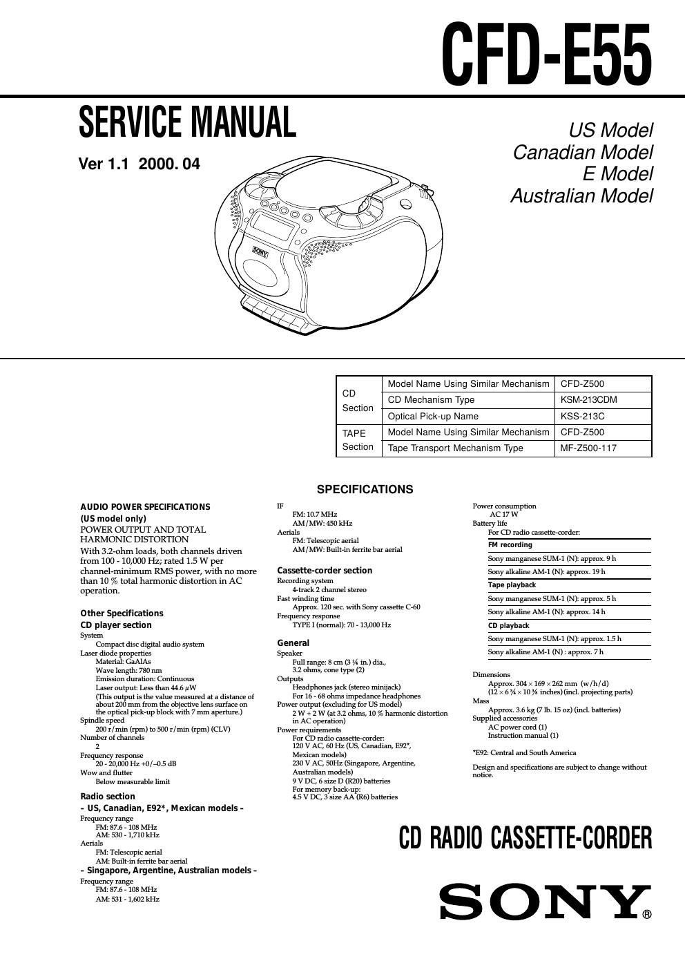
sony cfd e 55 service manual 1

Extracted text from sony cfd e 55 service manual 1 (Ocr-read)


Page 1

– 4 – MODEL TYPE IDENTIFICATION In this set, the routing of speaker lead wires and the boards have been changed in the midway of production, and the set is grouped into the following four types depending on the specifications. TYPE A: Original model. TYPE B: To the original model, the routing of speaker lead wires is changed. TYPE C: To the type B, the print patterns of board are changed. TYPE D: To the type C, the shapes of boards are changed. - Model Type Discrimination Identify each type from the part number printed on each board by referring to the following table. Also, each board is common to type A and type B, but routing of speaker lead wires is different. For details of different places, refer to 6. Diagrams 6-10. Printed Wiring Boards – MAIN/POWER SUPPLY Section (Type A, B) – (page 42, location A-1 and B-1). Type A, B Type C Type D Board Part No. BATT (+)1-675-297-11 1-675-297-12 1-677-315-11 BATT (–)1-675-298-11 1-675-298-12 1-677-316-11 CD1-675-290-11 1-675-290-12 1-677-308-11 CD MOTORin common to all types KEY 11-675-292-11 1-675-292-12 1-677-310-11 KEY 21-675-293-11 1-675-293-12 1-677-311-11 KEY 31-675-294-11 1-675-294-12 1-677-312-11 LCD1-675-295-11 1-675-295-12 1-677-313-11 LED *1 998-11 998-12 319-11 MAIN1-675-289-11 1-675-289-12 1-677-307-11 POWER1-675-291-11 1-675-291-12 1-677-309-11 REC SW1-675-296-11 1-675-296-12 1-677-314-11 *1) For the LED board, only the lower five digits of part number is printed. - Precaution on Replacing the Boards The supplied boards are all type D, and therefore if the board is replaced, use the board of type D only whichever model is serviced. However, on the type D model, the number of pins of connectors that connect MAIN board to CD board, and MAIN board to POWER board has been changed, and accordingly the type D is not interchangeable with type A, B, and C respectively. Therefore, if even one of MAIN, CD, and POWER boards is replaced, replace all three boards simultaneously. MODEL IDENTIFICATION  MODEL NO. CFD-E55 US, Canadian, E (AC 120V area), Mexican models: AC: 120 V 60 Hz 17 W Singapore, Argentine, Australian models: AC: 230 V - 50 Hz 17 W

Page 2

CFD-E55 – 19 –– 20 – SECTION 6 DIAGRAMS 6-1. BLOCK DIAGRAM – CD Section – A BD 4 7 6 4 7 6 F E C I-V AMP DETECTOR 39 38 17 18 26 27 2SL+ SL–SLO F– F+ T+ T– SPINDLE MOTOR DRIVE M701 (SPINDLE) S701 (LIMIT)SLED MOTOR DRIVE 1 M702 (SLED) FOCUS COIL DRIVE TRACKING COIL DRIVE SP+ SPO MUTE SP– 9 15 14 3 19 25 FIN TIN SLIN SPINSPI SLP FOCUS/TRACKING COIL DRIVE, SPINDLE/SLED MOTOR DRIVE IC702 16 14 SLED AMP LD PDLASER DIODE OPTICAL PICK-UP (KSS-213C) 2-AXIS DEVICE (FOCUS) (TRACKING) 33 32 27 35 18 2220211923 RF AMP, FOCUS/TRACKING SERVO IC701 (1/2)FOCUS OK COMPARATOR MIRR AMP DEFECT AMPFOCUS OK AMP IIL DATA REGISTER 3129 FILTER3330 FILO PCO CLTV FILI XPCK DIGITAL PLL ASYMMETRY CORRECTION EFM DEMODULATOR DIGITAL OUT ERROR CORRECTOR 16K RAM INTERNAL BUS SUB-CODE PROCESSOR OSC CLOCK GENERATOR SERVO AUTO SEQUENCER DIGITAL CLV 1412 41 43 39 13 79 5 4 6 7 9 8 57 58 59 62 70 1110 41 42 36 371 40 452 47 12 116 2524 13 PD1PD1 I-V AMP RFO RF 37ASYI 38 48ASYO FOK DATO CLKO XLTO SEIN CNIN MDP SQSO SQCK SENS DATA CLOK XLAT XLON SPOA SCOR SBSO EXCK XUGF WFCK EMPH EMPHI SYSM XTAI 71 XTAO RFI FOK DATA CLK SENS1 26 SENS2C.OUTXLT LOCK PD2 I-V AMP PD2 TTL IIL FEO TEO PDFEI FEO TAO TEI TTL IIL TTLIILXRST FOCUS ERROR AMP RF SUMMING AMP TRACKING ERROR AMPTRACKING PHASE COMPENSATIONFOCUS PHASE COMPENSATION AUTOMATIC POWER CONTROL Q701I-V AMP LD AMPPD AMPFE BIAS F E LDPCMD 53 DOUTBCK LRCKPCMDI BCKI LRCKI 42 44 40 50 C2PO SLED SERVO IC701 (2/2) 05DIGITAL SIGNAL PROCESSOR, CLV SERVO, D/A CONVERTER IC703 SYSTEM CONTROLLER IC501 (1/3) - SIGNAL PATH : CD PLAY 21 CPU INTERFACE D/A INTERFACE SERIAL INPUT INTERFACE PWM PWM OVER SAMPLING DIGITAL FILTERNOISE SHAPER 56 54 55AOUT2 65 XTSL 51 C4M 52 AOUT1 AIN2 AIN1 LOUT2 LOUT1 76 75 66 74 67 GFS X701 16.9344MHz 49 47 8 3 8 3 10 12 10 12 14 15 14 15 13 16 13 16 5 5CNP701 3 4 4 3CNP702 CNP707 + CD BOARD (1/2) CD MOTOR BOARD M 1 6 2 5 5 2 6 1 M XRST C-SCOR C-DOOR 1 78 C-LATCH 11 C-CLOCK 10 C-DATA 12 C-SENS 5 C-SQCK 7 C-SQSO 8 9 C-SENS2 6 C-RST C-SCORC-XLAT C-CLOKC-DATA C-SENS C-SQCK C-SQSO C-SENS2 C-XRST 17 15 7 S701 (CD LID OPEN/CLOSE DET)BH505BH701 (1/3) BH701 (2/3) BH701 (2/3)BH701 (1/3) 231 1 CNP703 74 56 8 1 3 2 9 BH503 74 56 8 1 3 2 9 R-CH L-CH BTO MAIN SECTION TYPE A: Page 23 TYPE B, C: Page 25 21 R-CH L-CH BTO MAIN SECTION (Page 27) FROM MAIN SECTION (TYPE A: Page 23) (TYPE B, C: Page 25) A LCD BOARD (1/3) TYPE A, B, C TYPE D 3 4 C-MUTE FROM MAIN SECTION (Page 27) A C-MUTE (TYPE D)