Sony cfd e 100 service manual

This is the 66 pages manual for sony cfd e 100 service manual.
Read or download the pdf for free. If you want to contribute, please upload pdfs to audioservicemanuals.wetransfer.com.

Page: 1 / 66
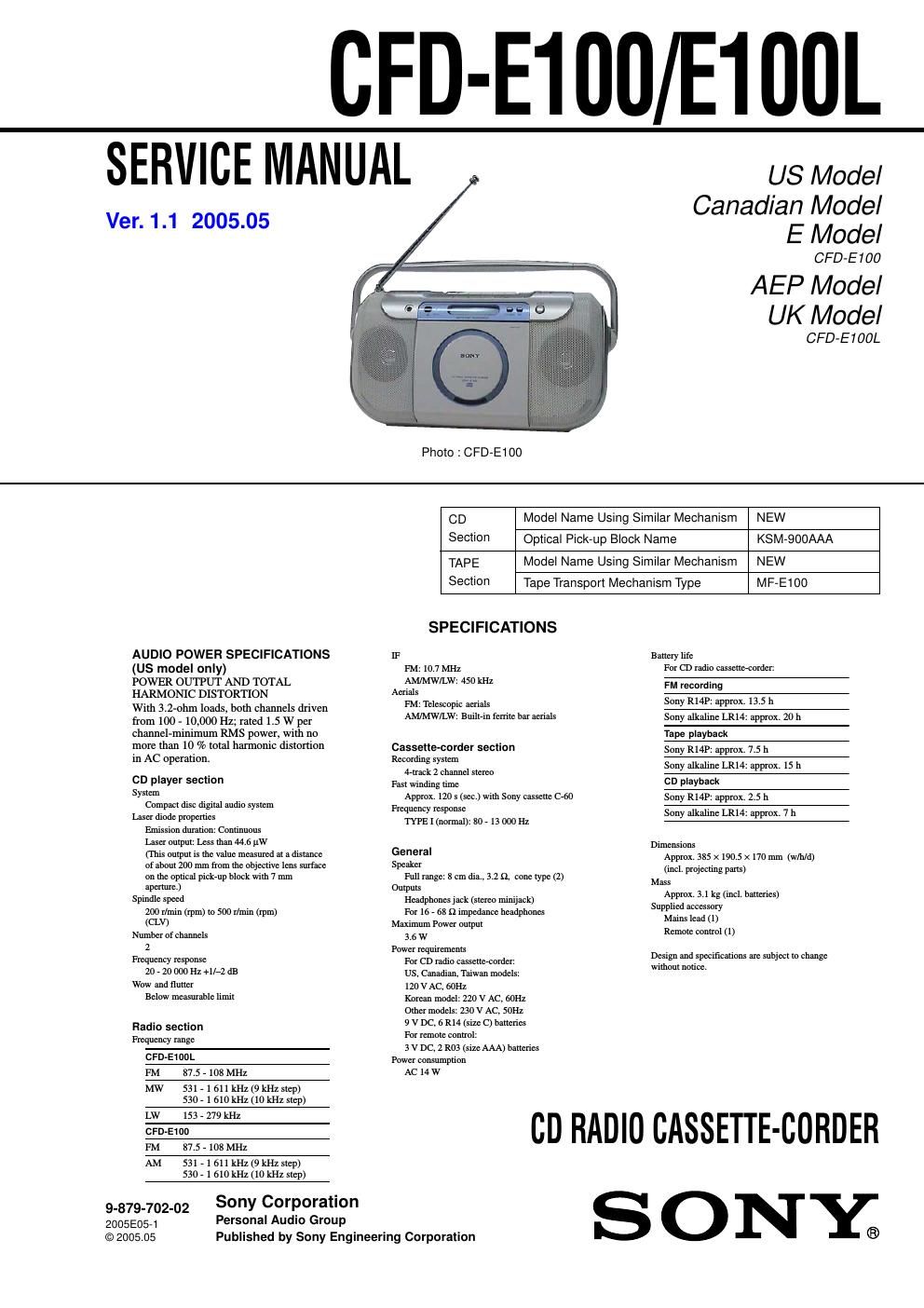
sony cfd e 100 service manual

Extracted text from sony cfd e 100 service manual (Ocr-read)


Page 1

CFD-E100/E100L

SERVICE MANUAL

Ver. 1.1 2005.05

US Model
Canadian Model
E Model

CFD-E100
AEP Model
UK Model

CFD-E100L
Photo : CFD-E100
CD Model Name Using Similar Mechanism NEW
Section Optical Pick-up Block Name KSM-900AAA
TAPE Model Name Using Similar Mechanism NEW
Section Tape Transport Mechanism Type MF-E100
SPECIFICATIONS
AUDIO POWER SPECIFICATIONS 1F Bailery Ilfc
(US model only) FM 10.7 MHz For CD radio casseiio-eorder:
POWER OUTPUT AND TOTAL AM/MW/LW= 450 kHz FM recording
HARMONIC DISTORTION Aerials . >
Will] 3.2»ohm loads, both channels driven FM} Tammy; WIS , .
AM/MW/LW: Bran-in fomle oar aei-ials . approx. 20 h

from 100 - 10,000 Hz; rated 1.5 W per
channel»minimum RMS power, will-1 no
more than 10 % total harmonic disrortion
in AC operation.

CD player section
Sysrem
Compacr disc digilal audio sysreni
Laser diode properties
Emission duraiion: Conlinuous
Laser ouipul: Less lhan 44.6 law
(This oulpui is me value measured or a disianee
oi aoour 200 mm from lhe objeciiye lens suriaec
on ihe oplical pick-up block wiih 7 mm
apenure)
Spindle speed
200 mm (rpm) ro 500 r/min (rpm)
(CLV)
Number of channels
2
Frequency response
20 » 20 000 Hz+ll~2 dB
WOW and finite!
Below measurable limir

Radio section

Frequency range
CFD-EmoL
FM 87.5 - 103 MHz

MW 531-1611kHz(9kstiep)
530-1610kHz(10kstiep)

LW 153 - 279 kHz
CFD-E100
FM 87.5 - 108 MHZ

AM 531-1611kHz(9kstl,ep)
530-1610kHz(10kstlep)

9-879-702-02
2005120571
© 2005.05

Personal Audio Gro

Cassene-corder section
Recording sysreni
4-lrnek 2 channel sroreo
Fasi winding rime
Approx. 124) s lsco.) wiLh Sony cassonc C-60
Frequency response
TYPE] (normal): 80 » 13 000 Hz

General
Speaker

Full range 23 em dia. 3.2 9, Cone iype (2)
Onrpurs

Headphones jack (siereo minijaek)

For 16 - 68 n impedance headphones
Maximum Power ouipul

3.5 w
Power requirements

For CD radio cassene-wrder

US. Canadian, Taiwan models:

120 v AC, 60Hz

Korean model: 220 v AC, 601-12

omer models: 230 v AC. 501-12

9 v DC. 6 R14 (size C) balreries

For remore comm!

3 v Dc, 2 R03 (sizo AAA) oancrios
Power consumpiion

AC 14 w

Tape playback
Sony R14P: approx. 7.5 li

Sony alkaline LR14. approx. 15 h
on playback

Sony R141): approx. 2.5 li

Sony alkaline LR14. approx. 7 h

Dimensions
Approx. 335 x 190.5 x 170 mm (th/d)
(incl, projecring pans)

Mass
Approx. 3.1 kg (incl. oaricries)

Supplied accessory
Mains lead (1)

Remole comm! (1 )

Design and speeificarions are subject to change
wilholll noiice.

CD RADIO CASSETTE-CORDER

Sony Corporation

up

Published by Sony Engineering Corporation

SONYe

Page 2

CFD-E100/E100L

CAUTION

Use of controls or adjustments or performance of procedures
other than those specified herein may result in hazardous radiation
exposure.

Notes on chip component replacement
I Never reuse a disconnected chip component.
0 Notice that the minus side of a tantalum capacitor may be
damaged by heat.

Flexible Circuit Board Repairing
- Keep the temperature of the soldering iron around 270 C
during repairing.
- Do not touch the soldering iron on the same conductor of the
circuit board (within 3 times).
0 Be careful not to apply force on the conductor when soldering
or unsoldering.

Abqu CD-RS/CD-RWS

This player can play CDrRs/CDVRWs
recorded In the CDVDA format", but
playback capability may vary depending on
the qunhty ot the disc and the coudmon of
the recording device.

6 CDVDA IS the abbreviation for Compact
Disc Digital Alldto. 11 IS a recording
standard used for Audio CDs.

SAFETY CHECK-OUT

After correcting the original service problem, perform the following
safety check before releasing the set to the customer:

Check the antenna terminals, metal trim, metallized knobs, screws,
and all other exposed metal parts for AC leakage.

Check leakage as described below.

LEAKAGE TEST

The AC leakage from any exposed metal part to earth ground and
from all exposed metal parts to any exposed metal part having a
return to chassis, must not exceed 0.5 mA (500 microamperes.).
Leakage current can be measured by any one of three methods.

1. A commercial leakage tester, such as the Simpson 229 or RCA
WT-540A. Follow the manufacturers instructions to use these
instruments.

2. A battery-operated AC milliammeter. The Data Precision 245
digital multimeter is suitable for this job.

3. Measuring the voltage drop across a resistor by means of a
VOM or battery-operated AC voltmeter. The limit indication
is 0.75 V, so analog meters must have an accurate low-voltage
scale. The Simpson 250 and Sanwa SH-63Trd are examples
of a passive VOM that is suitable. Nearly all battery operated
digital multimeters that have a 2VAC range are suitable. (See

Fig. A)
To Exposed Metal
Pants on Set
AC
0.15uF g 1.5 kfl / voltmeter
(0. 75 V)

_:_ Earth Ground
Fig. A. Using an AC voltmeter to check AC leakage.

2

SAFETY-RELATED COMPONENT WARNING!!

COMPONENTS IDENTIFIED BY MARK A OR DOTTED LINE
WITH MARK A ON THE SCHEMATIC DIAGRAMS AND IN
THE PARTS LIST ARE CRITICAL TO SAFE OPERATION.
REPLACE THESE COMPONENTS WITH SONY PARTS WHOSE
PART NUMBERS APPEAR AS SHOWN IN THIS MANUAL OR
IN SUPPLEMENTS PUBLISHED BY SONY.

ATTENTION AU COMPOSANT AVANT RAPPORT
A LA SECURITE!

LES COMPOSANTS IDENTIFIES PAR UNE MARQUE A SUR
LEs DIAGRAMMES SCHEMATIQUES ET LA LISTE DES
PIECES SONT CRITIQUES POUR LA sEcuanE DE
FONCTIONNEMENT. NE REMPLACER CEs com- POSANTS
QUE PAR DES PIECES SONY DONT LES NUMEROS SONT
DONNES DANS CE MANUEL ou DANS LES SUPPLEMENTS
PUBLIES PAR SONY.