Sony cfd dw 83
This is the 40 pages manual for sony cfd dw 83.
Read or download the pdf for free. If you want to contribute, please upload pdfs to audioservicemanuals.wetransfer.com.
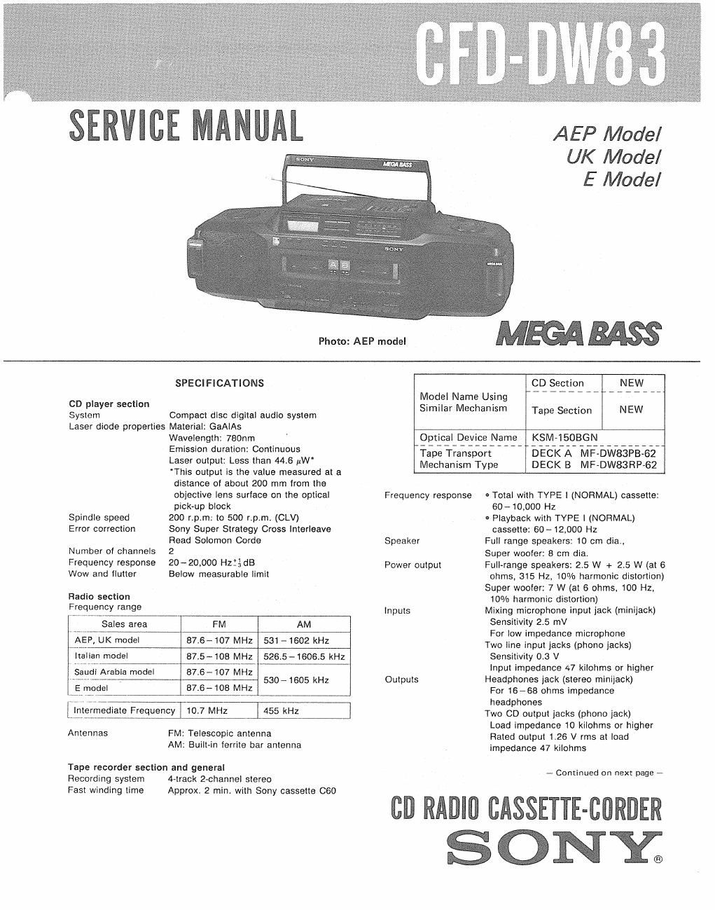
Extracted text from sony cfd dw 83 (Ocr-read)
Page 1
gin
gt
Photo: AEP model
AEP Model
UK Model
E Model
MEGABASS
CD player section
System
SPECIFICATIONS
Compact disc digital audio system
Laser diode properties Material: GaAIAs
Spindle speed
Error correction
Number of channels
Frequency response
Wow and flutter
Radio section
Frequency range
Wavelength: 780nm
Emission duration: Continuous
Laser output: Less than 446 th'
This output is the value measured at a
distance of about 200 mm from the
objective lens surface on the optical
pick-up block
200 rpm: to 500 rpm. (CLV)
Sony Super Strategy Cross interleave
Read Solomon Corde
2
20 -20,000 Hzié dB
Below measurable limit
E model
Sales area FM AM
AEP, UK model 87,6- 107 MHz 531 - 1602 kHz
italian model 875- 108 MHz 5265-16065 kHz
S udi Arabia model 87.6-- 107 MHZ
~~ , 530-1605 kHz
87.6- 108 MHz
455 kHz
Anlennas
FM: Telescopic antenna
AM: Built-in ferrite bar antenna
Tape recorder section and general
Recording system
Fast winding time
4~track 2-channel stereo
Approx. 2 min with Sony cassette C60
Model Name Using
Similar Mechanism
CD Section
Tape Section
Optical Device Name
Tape Transport
Mechanism Type
KSM-iSOBGN
DECK A MF»DW83PB-62
DECK B MF-DW83RP-62
Frequency response
Speaker
Power output
inputs
Outputs
- Total with TYPE I (NORMAL) cassette:
60- 10.000 Hz
- Playback with TYPE I (NORMAL)
cassette: 60-12000 Hz
Full range speakers: 10 cm dia.,
Super woofer: 8 cm dia,
Full-range speakers: 25 W + 25 W (at 6
ohms, 315 Hz, 10% harmonic distortion)
Super woofer: 7 W (at 6 ohms, 100 Hz.
10% harmonic distortion)
Mixing microphone input jack (minijack)
Sensitivity 25 mV
For low impedance microphone
Two line input jacks (phono jacks)
Sensitivity 0.3 V
input impedance 47 kiiohms or higher
Headphones jack (stereo minijack)
For 16-68 ohms impedance
headphones
Two CD output jacks (phono jack)
Load impedance 10 kilohms or higher
Rated output 1.26 V rms at load
impedance 47 kilohms
- Continued on next page 7
cu RADIO CASSETTE-BORDER
S ONE
Page 2
CFD-DW83
Power requirements 12V DC, eight R20 (size D) batteries
tor CD radlo cassette-corder
4.5V DC, three R6 (size AA) batteries for
clock/timer
Requirements
UK model 240V AC. 50H:
AEP model 220V AC, 50H:
E model 110~120V, 220-240V AC.
adiustable, 50/60Hz
Power consumption
UK model 30 W
AEP model 28 W
E model 35 W
Battery life Batteries for radio cassette-comer
Recording Playback CD playing
Sony SUMJ (NS) approx. 2.5H approx. 2H approx. 1H
Sony Alkaline
AM1 (N) approx. 3.5H approx. 3H approx. 1.5H
Dimensions 636.5 x 211 x 226 mm (w/hld)
(25% x 8% x 9 inches)
incl. projecting parts and controls
Weight Approx. 8.3 kg, incl. batteries
(Approx. 18 lb 4.8 oz)
Supplied accessory AC power cord (1)
Note
This appliance conforms with EEC Directives 76/389 and 82/499
regarding interference suppression.
Design and specifications subject to change without notice.
SAFETY-RELATED COMPONENT WARNING
COMPONENTS IDENTIFIED BV MARK A OR DOTTED
LINE WITH MARK A ON THE SCHEMATIC DIAGRAMS
AND IN THE PARTS LIST ARE CRITICAL T0 SAFE
OPERATION. REPLACE THESE COMPONENTS WITH
SONY PARTS WHOSE PART NUMBERS APPEAR AS
SHOWN IN THIS MANUAL OR IN SUPPLEMENTS PUB-
LISHED BY SONY.
TABLE OF CONTENTS
Section Title Page
Specifications ....................... 1
1. SERVICING NOTES
4-1.
4-2.
5.
5-1.
5-2.
5-3.
5-4.
5-5.
57.
5-8.
Model Identification ............... 3
Notes on Handling the Optical Pick-up
Block or Base Unit ................ 3
Chuck Plate Jig on Repairing ......... 4
G ENERAL
Location and Function of Controls ..... 5
Setting the Clock ................. 6
Using the Built-in Timer ............. 6
DISASSEMBLY .................. 7
ADJUSTMENTS
Mechanical Adjustment ............. 10
Electrical Adjustments .............. 1 1
Tape Recorder Section ............. 1 1
Radio Section ................... 12
CD Section ..................... 14
DIAGRAMS
Radio, Audio Section Block Diagram . . . . 18
CD Section Block Diagram ........... 21
Radio Section Printed Wiring Boards and
Schematic Diagram ................ 24
Tape Recorder Section
Schematic Diagram ................ 27
Power Amp, Power Supply Section
Schematic Diagram ................ 30
Tape Recorder, Power Amp, Power Supply
Section Printed Wiring Boards ......... 33
CD Section Schematic Diagram . . . 37
CD Section Printed Wiring Board ....... 41
EXPLODED VIEWS ............... 46
ELECTRICAL PARTS LIST ......... 56