Sony cdx u 404 service manual

This is the 2 pages manual for sony cdx u 404 service manual.
Read or download the pdf for free. If you want to contribute, please upload pdfs to audioservicemanuals.wetransfer.com.

Page: 1 / 2
sony cdx u 404 service manual

Extracted text from sony cdx u 404 service manual (Ocr-read)


Page 1

CDX-U404

S ONY: US Model

SERVICE MANUAL \ Canadian Model

AEP Model
E Model

SUPPLEMENT-1

File this supplement with the service manual.

Subject: Mechanical Adlustment

Electrical Adjustments
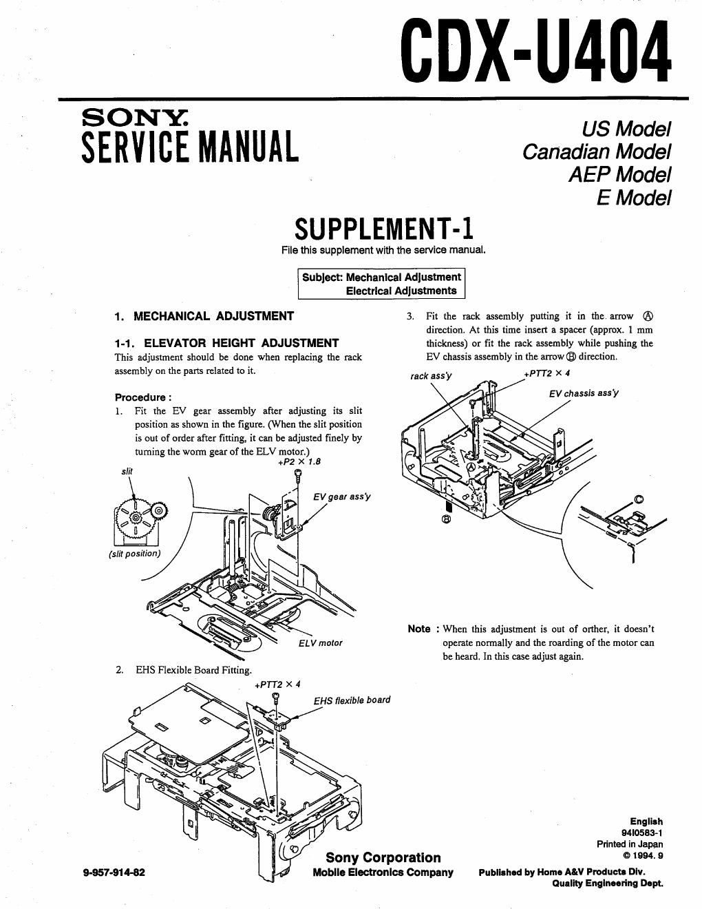
1. MECHANICAL ADJUSTMENT 3 Fit the rack assembly putting it in the arrow ®
direction. At this time insert a spacer (approx. 1 mm
1-1. ELEVATOR HEIGHT ADJUSTMENT thickness) or fit the rack assembly while pushing the
This adjustment should be done when replacing the rack EV chassis assembly in the arrow® direction
assembly on the pans related to it. lack 555.}, +PTTZ x 4

Procedure :

1. Fit the EV gear assembly after adjusting its slit
position as shown in the figure. (When the slit position
is out of order after fining, it can be adjusted finely by

fuming the worm gear of the ELV motor.)
+P2 X 1.8
slil


E V gear ass-y 0
\*/
¢ ll \ '
\ /
(slit position) 7

Note : When this adjustment is out of orther, it doesnt
operate normally and the roarding of the motor can
be heard In this case adjust again.

2. EHS Flexible Board Fitting.

' +PTl2 x 4

EH5 flexible board

English
94l0533-1
Printed in Japan
Sony Corporation 01994.9

Moblle Electronlcs Company Published by Home MN Products Div.
Ouallly Englneoring Dept

9-957-91 4-82

Page 2

2. ELECTRICAL ADJUSTMENTS

1. Perform adjustments as given.
Be sure to use the disc YEDS-ls" parts code : 3-702-101-01, but
only when indicated.

3. Power supply voltage : DC 144 V (more than 3A).

2-1. FOCUS OFFSET ADJUSTMENT
Procedure:
[SERVO BOARD] - Conductor Side -
oscilloscope
RV12 L +
g e
f l
~ : i?»
_ _ l l .1 i
n I
Z Z

41

1. Connect the oscilloscope to SERVO board test point
2. Put the set into play mode by loading the disc.
3. Adjust (SERVO board) RV12 so that the oscilloscope.
Waveform eye pattern is good.
( A good eye pattern means that the diamond shape (0) in the )
center of the oscilloscope can be clearly distinguished

200 mV
0.5 [4896

Volt/Div :
Time/Div :

1.0:36 Vp-p

2-2. TMCKING OFFSET ADJUSTMENT
Procedure :

[SERVO BOARD] - Conductor Side -

oscllloscope

RV"
' A
.._. V
Z Z
I
m I
I Z
to H
'
rm ' c
3 .
.u I

1. Connect the oscilloscope to SERVO board test point I, pin Q) of
ICU.

2. Put the set into play mode by loading the disc.

Press the I44 AMS m button. then, check the traverse waveform"

4. Adjust RVll (SERVO board) so that the oscilloscope reading is
symmetrical in relation to 0 V.
Traveisewavefonnz'lhis is the tracking error waveform appears

when crossing the track.

93

Volt/Div : 0.5 V
Time/Div: 2 mSec
Center a V

A:

"avers waveform
(100 track jump waveform)