Sony cdx r 77 service manual

This is the 53 pages manual for sony cdx r 77 service manual.
Read or download the pdf for free. If you want to contribute, please upload pdfs to audioservicemanuals.wetransfer.com.

Page: 1 / 53
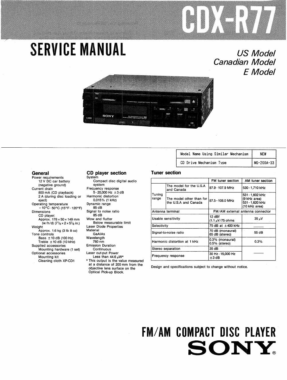
sony cdx r 77 service manual

Extracted text from sony cdx r 77 service manual (Ocr-read)


Page 1

SERVICE MANUAL

US Model
Canadian Model

E Model

General
Power requirements
12 V DC car battery
(negative ground)
Current draln
800 mA (CD playback)
2 A (during disc loading or
eject)
Operating temperature
-10°C-50°C (15°F»120°F)
Dimensions
CD player:
Approx. 178 x 50 x 149 mm
(w/h/d) (71/5 x 2 x 57/3 in)
Weight
Approx, 16 kg (3 lb 8 oz)
Tone controls
Bass :10 dB (100 Hz)
Treble : 10 dB (10 kHz)
Supplied accessories
Mounting hardware (1 set)
Optional accessories
Mountlng klt
Cleaning cloth XP-CDl

CD player section
System
Compact disc digital audlo
system
Frequency response
5~20,000 Hz :3 dB
Harmonic distortion
0.015% (1 kHz)
Dynamic range
85 dB
Signal to noise ratio
85 dB
Wow and flutter
Below measurable Ilmit
Laser Diode Properties
Materiel
GaAlAs
Wavelength
780 nm
Emission Duratlon
Continuous
Laser out-put Power
Less than 44.6 uW

Thls output is the value measured
at a distance 0! 200 mm from the
objective lens surlace on the
Optical Plck-up Blocki

Model Name Using Similar Mechanisn

NEW

CD Drive Mechanism Type

MG-ZOOA-33

Tuner section

FM tuner sectlon

AM tuner section

The model for the USA

and Canada 873-1019 MHZ 530»1,710KH2
Tunlng 531-1502 kl-iz
range The model other than for _ (9 kHz area)

the U.S.A and Canada 87'5 108 MHZ 531-1520 kHz

(10 kHz area)

Antenna terminal

FM/AM external antenna connector

12 dBf

Usable sensltivity (1'1 uV/75 ohms 35uV

Selectivity 75 dB at 2400 kHz _
_ , 70 dB (monaural)

Slgnal tonorse ratlo 65 dB (stereo) 55 dB

Harmonic distortion at 1 kHz 03% (new) 0.3%

0.5% (stereo)

Stereo separation

35 dB

Frequency response

30 Hz-15,000 Hz
:3dB

Design and specifications subject to change without notice.

FM/AM CUMPACT msc PLAYER
SONY;

Page 2

CDX-R77

TABLE OF CONTENTS

Tit 1e Sect ion Page
SPECIFICATIONS .................................. 1

Notes on Chip Component Replacement ~~~~~~~~~ 2

Notes on Handling the Optical Pick-up Block

or Base Unit .................................. 2
SECTION 1. GENERAL

Location of Controls .......................... 3
SECTION 2. SERVICING NOTES

Removing the Flat Package IC ~~~~~~~~~~~~~~~~~~ 4

Flexible Circuit Board Repairing~ -

Cautions for Repair ------------

Test Mode ..................................... 5
SECTION 3. CIRCUIT DESCRIPTION ---------------- 7

ICl Pins (CXP5068H-0080) ---------
10501 Pins (CXP5048H-1880) ------

SECTION 4. MECHANICAL ADJUSTMENTS ~~~~~~~~~~~~~~~ 11
SECTION 5. ELECTRICAL ADJUSTMENTS --------------- 11
SECTION 6. DIAGRAMS

6-1. Block Diagram(MD Section) ~~~~~~~~~~~~~~~~~ 15
6 2. Block Diagram (Main Section) ~ - - - - - - ' l7
6- 3. Semiconductor Lead Layouts ~~~~~~~ 19
6- 4. Printed Wiring Boards (MD Section) .. ~ 20
6 5. Schematic Diagram (MD Section) - 23
6- -6. Circuit Boards Location 1 -------- ~ 26
6- 7. Printed Wiring Boards (Main Section) 27
6- 8. Schematic Diagram (Mam Section) - 31
6- 9. Schematic Diagramll'uner Section) ~ 35
6 10. IC Block Diagrams -------------- - 36
6-11. Waveforms ~~~~~~~~ 38
SECTION 7. EXPLODED VIEW ----------------------- 40
SECTION 8. ERECTRICAL PARTS LIST .......................... 48
SUPPLEMENT- 1 .................................................................... 57

SERVICING NOTE

Flexible Circuit Board Repairing

0 Keep the temperature of the soldering iron around
270°C during repairing.

0 Do not touch the soldering iron on the same con-
ductor of the circuit board (within 3 times).

0 Be careful not to apply force on the conductor
when soldering or unsoldering.

Notes on chip component replacement

0 Never reuse a disconnected chip component.
0 Notice that the minus side of a tantalum capacitor
may be damaged by heat.

SA FETV~RELATED COMPONENT WARNING! l

COMPONENTS IDENTIFIED 8V MARK A OR DOTTED

LINE WITH MARK A ON THE scHEMATIc DIAGRAMS

AND IN THE PARTS LIST ARE CRITICAL T0 SAFE

OPERATION. REPLACE THESE COMPONENTS WITH

SONY PARTS WHOSE PART NUMBERS APPEAR As

SHOWN IN Tms MANUAL OR IN sUPPLEMENTs PUB-
' LISHED 3v SONY.

Removing the Flat Package IC

1. Prepare an enameled wire (0.3mm diameter) and
apply it to the back side of the IC pins as illus»
trated below.

Solder or fix with adhesive tape.

2. Heat the 10 pin with the soldering iron and draw
the enameled wire so that the 10 pin is removed
from thepattern as illustrated.

ATTENTION AocoMPOSANT AYANT RAPPORT
A LA SECURITEI

LEs COMPOSANTS IDENTIFIEs PAR UNE MAROUE A
son LEs DIAGRAMMES scuéMATIouEs ET LA LIsTE
DES PIEOEs sow-r cmTIouEs POUR LA sEcURnTE
DE FONCTIONNEMENT. NE REMPLACER was com.
POSANTS ouE PAR DES PIECES SONY DONT LES
NUMERos sONT DONNES DANS CE MANUEL ou
DANS LEs SUPPLEMENTS PuaLIEs PAR SONY.

_2__