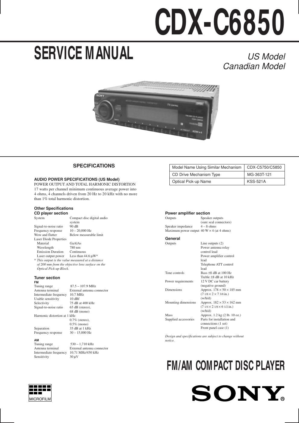
Sony cdx c 6850 service manual
This is the 13 pages manual for sony cdx c 6850 service manual.
Read or download the pdf for free. If you want to contribute, please upload pdfs to audioservicemanuals.wetransfer.com.
Extracted text from sony cdx c 6850 service manual (Ocr-read)
Page 1
Ð 20 Ð 4-1. IC PIN DESCRIPTION ¥ IC801 MB90574PFV-G-179-BND (SYSTEM CONTROL) Pin No. Pin Name I/O Pin Description 1 LD ON O Laser ON/OFF control output 2 FOK I Focus OK signal detection input 3 XLAT25 O CD signal processing latch output 4 DATA25 O CD signal serial data output 5 XRST O Reset output to CD signal processor IC. 6 GFS I GFS signal detection input 7 NIL Ñ Not used. (Connect to ground in this set.) 8 VCC Ñ Power supply pin (+5 V) 9 Ð 11 NIL Ñ Not used. (Open) 12 FLS SI/NOSE1 I Front panel attachment detection input 13 LCD SO/FLS SO O LCD serial data output 14 LCD CKO O LCD serial clock output 15 BEEP O BEEP output 16 NIL Ñ Not used. (Open) 17 SQ SI I Sub Q data input 18 NIL Ñ Not used. (Connect to ground in this set.) 19 SQ CKO O Sub Q read clock output 20 UNI SI I BUS system serial interface input 21 UNI SO O BUS system serial interface output 22 UNI CK I/O BUS system serial clock input/output 23 C IN I Track jump No. count input 24 SIRCS I Remote commander input 25 TXT SI I CD-TEXT data input 26 NIL Ñ Not used. (Connect to ground in this set.) 27 TXT CKO O CD-TEXT data read clock output 28 CLOK25 O CD signal processing serial clock output 29 SYSRST O System reset output 30 DEEMPH O De-emphasis output 31 AMP ATT O Power amplifier attenuator control output 32 MD ON O CD mechanism power control output 33 VSS Ñ Ground 34 C Ñ Power stabilization capacitor pin 35 CD ON O CD power control output 36 BUS ON O BUS ON control output 37 AD ON O Power control output of A/D conversion. 38 DVCC Ñ VREF input of D/A converter. 39 DVSS Ñ Ground of D/A converter. 40 NIL Ñ Not used. (Open) 41 ANGLE O LCD view angle alignment output (Not used in this set.) 42 AVCC Ñ Analog power supply pin (+5 V) 43 AVRH Ñ VREF + input of A/D converter. 44 AVRL Ñ VREF Ð input of A/D converter. 45 AVSS Ñ Analog ground 46 Ð 48 KEY IN0 Ð 2 I Key input 0 Ð 2 49 RC IN0 I Rotary commander input 0 50 QUALITY I Not used in this set. 51 NIL Ñ Not used. (Connect to ground in this set.) 52 MPDH I Tuner multi path input (Not used in this set.) 53 S-METER I S-meter voltage detection input 54 VCC Ñ Power supply pin (+5 V) 55 NS MASK O Not used in this set. SECTION 4 DIAGRAMS
Page 2
Ð 21 Ð Pin No. Pin Name I/O Pin Description 56 AMP ON O Power amplifier power control output 57 TXT ON O Reset output to CD-TEXT decoder IC. 58 VOL ATT O Electric volume mute control output 59 NIL Ñ Not used. (Open) 60 ATT O System attenuate control output 61 RC IN1 I Rotary commander shift key input 1 62 TU ATT O Tuner attenuate output (Not used in this set.) 63 VSS Ñ Ground 64 NIL Ñ Not used. (Open) 65 SSTOP I IF counter result signal detection input of PLL. 66 TEST I Test mode initial setting detection input 67 DAVN I RDS IC data acquisition detection input (Fixed at ÒLÓ in this set.) 68 FM ON/AM ON O FM ON output 69 TU ON O Tuner power control output 70 SDA I/O I 2C BUS serial data input/output 71 SCL O I 2C BUS serial clock output 72 NOSE2 I Front panel OPEN detection input (Not used in this set.) 73 X1A O Sub ceramic oscillator output (32 kHz) 74 X0A I Sub ceramic oscillator input (32 kHz) 75 SCOR I SCOR signal detection input 76 BU IN I Backup power detection input 77 DQSY I CD-TEXT data setting completion signal detection input 78 CD SENS I CD SENS signal detection input 79 KEY ACK I Key input acknowledge 80 TEL ATT I Telephone attenuate detection input 81 ST/MONO I/O Tuner stereo signal detection input/forced monaural output 82 SEEKOUT O SEEK output 83 SD IN I Signal detector input 84 WIDE O WIDE/NARROW select output (Not used in this set.) 85 NARROW O WIDE/NARROW select output (Not used in this set.) 86 HSTX Ñ Hardware standby input (Connect to pin (¼ (RESET).) 87 MD2 Ñ Operation mode input (Connect to ground in this set.) 88, 89 MD1, 0 Ñ Operation mode input (Connect to VCC in this set.) 90 RESET I Reset input 91 VSS Ñ Ground 92 X0 I Main ceramic oscillator input (4.19 MHz) 93 X1 O Main ceramic oscillator output (4.19 MHz) 94 VCC Ñ Power supply pin (+5 V) 95 COM8V ON O COM 8V control output 96 NIL Ñ Not used. (Open) 97 AREA1 I Destination select input 1 (Fixed at ÒLÓ in this set.) 98 AREA2 I Destination select input 2 (Fixed at ÒLÓ in this set.) 99 AREA3 I Destination select input 3 (Fixed at ÒHÓ in this set.) 100 BAND I Not used in this set. 101 ACC IN I Accessory power detection input 102, 103 PH3, 2 I Disc insertion detection photo sensor input (Not used in this set.) 104 LCD CE O LCD chip enable output 105 FLS W I Flash write input (Fixed at ÒHÓ in this set.) 106, 107 RE IN0, 1 I Rotary encoder input 108 ILL ON O Illumination power control output 109 PW ON O System power control output 110 NIL Ñ Not used. (Open) 111 ANT REM O ANT REMOTE power control output