Sony cdx c 4840 r service manual

This is the 56 pages manual for sony cdx c 4840 r service manual.
Read or download the pdf for free. If you want to contribute, please upload pdfs to audioservicemanuals.wetransfer.com.

Page: 1 / 56
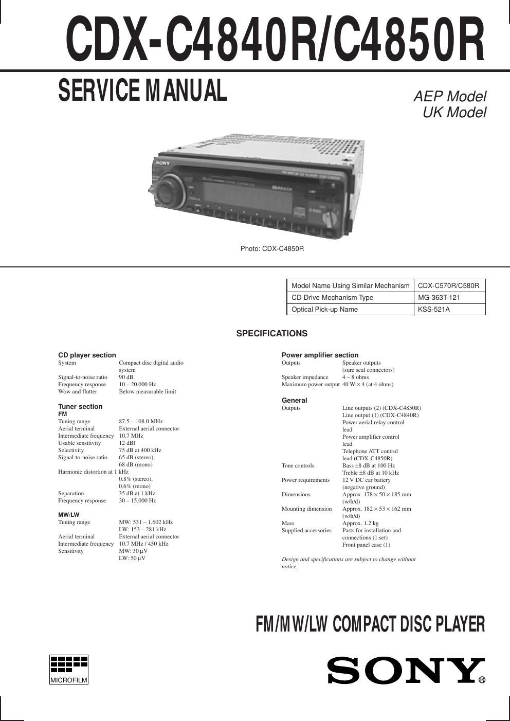
sony cdx c 4840 r service manual

Extracted text from sony cdx c 4840 r service manual (Ocr-read)


Page 2

Ð 3 Ð TABLE OF CONTENTS 1. GENERAL Location of controls ................................................................. 4 Getting Started ......................................................................... 4 Setting the clock ...................................................................... 4 CD Player ................................................................................ 4 Radio ....................................................................................... 5 RDS ......................................................................................... 5 Other Functions ....................................................................... 7 CD/MD Unit ............................................................................ 8 Connections ........................................................................... 10 2. DISASSEMBLY 2-1. Cover ................................................................................. 12 2-2. Front Panel Assy ............................................................... 12 2-3. Sub Panel (1) Assy ............................................................ 13 2-4. CD Mechanism Block ....................................................... 13 2-5. Main Board ....................................................................... 14 2-6. Heat Sink ........................................................................... 14 2-7. Chassis (T) Sub Assy ........................................................ 15 2-8. Lever Assy ......................................................................... 15 2-9. Servo Board ....................................................................... 16 2-10. Roller Assy ........................................................................ 16 2-11. Chassis (OP) (O/S) Assy ................................................... 17 2-12. Optical Pick-up Block ....................................................... 17 3. ELECTRICAL ADJUSTMENTS Tuner Section ......................................................................... 18 CD Section ............................................................................ 21 4. DIAGRAMS 4-1. IC Pin Description ............................................................. 22 4-2. Block Diagram ÐCD SectionÐ ........................................... 25 4-3. Block Diagram ÐTuner SectionÐ ....................................... 27 4-4. Block Diagram ÐDisplay SectionÐ .................................... 29 4-5. Circuit Boards Location .................................................... 31 4-6. Printed Wiring Boards ÐCD Mechanism SectionÐ ............ 33 4-7. Schematic Diagram ÐCD Mechanism SectionÐ ................ 35 4-8. Printed Wiring Board ÐMain SectionÐ .............................. 37 4-9. Schematic Diagram ÐMain Section (1/3)Ð ........................ 41 4-10. Schematic Diagram ÐMain Section (2/3)Ð ........................ 43 4-11. Schematic Diagram ÐMain Section (3/3)Ð ........................ 45 4-12. Schematic Diagram ÐDisplay SectionÐ ............................. 47 4-13. Printed Wiring Board ÐDisplay SectionÐ .......................... 49 5. EXPLODED VIEWS 5-1. Chassis Section ................................................................. 55 5-2. Front Panel Section ........................................................... 56 5-3. CD Mechanism Section (1) ............................................... 57 5-4. CD Mechanism Section (2) ............................................... 58 5-5. CD Mechanism Section (3) ............................................... 59 6. ELECTRICAL PARTS LIST ........................................ 60