Sony cdx a 35 rf service manual

This is the 27 pages manual for sony cdx a 35 rf service manual.
Read or download the pdf for free. If you want to contribute, please upload pdfs to audioservicemanuals.wetransfer.com.

Page: 1 / 27
sony cdx a 35 rf service manual

Extracted text from sony cdx a 35 rf service manual (Ocr-read)


Page 1

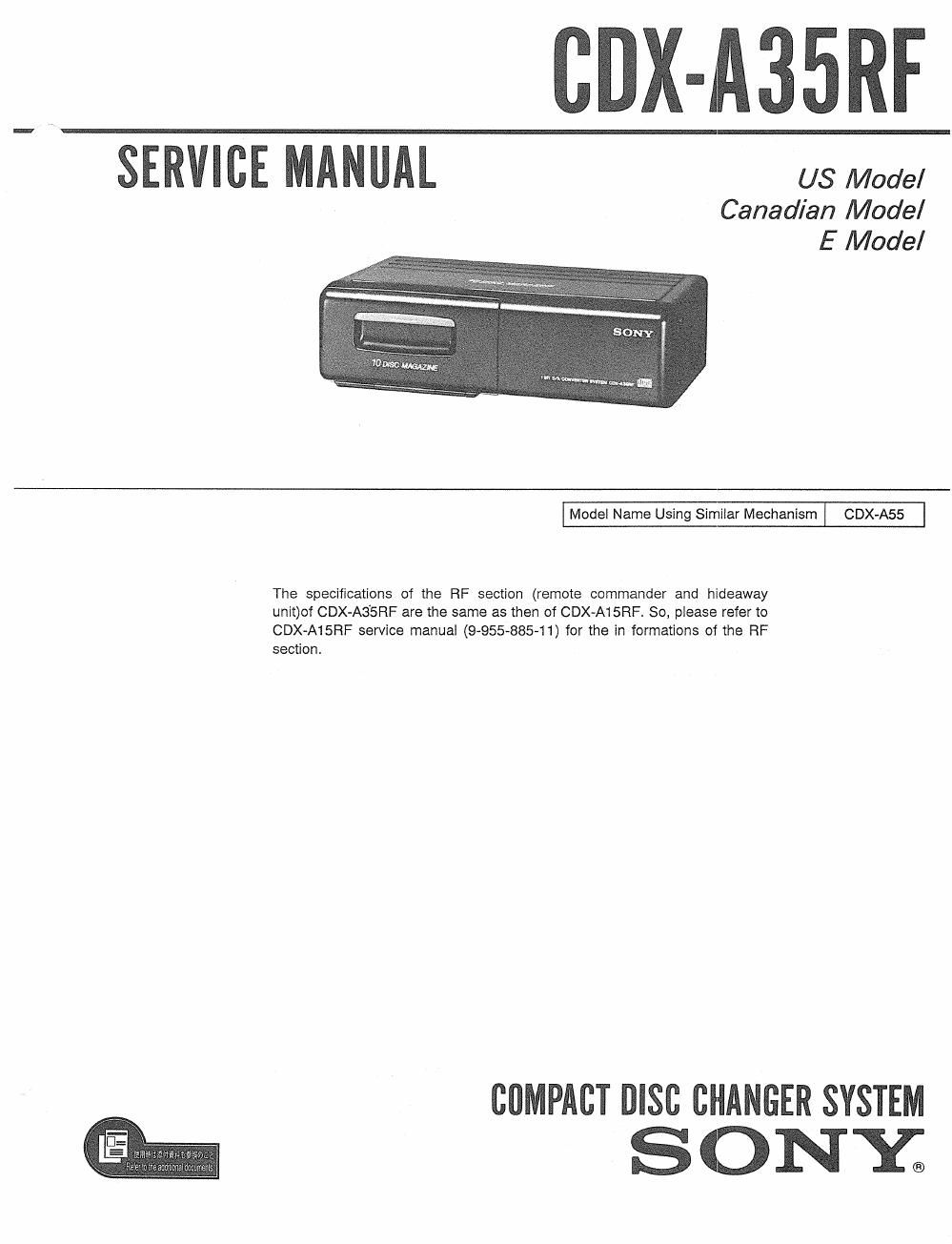
CDX-A35RF

SERVICE MANUAL us Model

Canadian Model
E Model

I Model Name Using Similar Mechanism CDX-A55

The specifications of the RF section (remote commander and hideaway
unit)of CDX-A35RF are the same as then of CDX-A15RF. So, piease refer to
CDX»A15RF service manual (9955-88541) for the in formations of the RF
section.

COMPACT DISC CHANGER SYSTEM

SONY;

Page 2

SPECIFICATIONS

CD changer
System Compact disc digital audio System
Laser diode properties
Material: GaAlAs
Wavelength: 780 nm
Emission duration: Continuous
Laser oulput power: Less than 44.6 uW"
* This output Is the value measured at a
distance 0! 200 mm from the objective

lens surface on the Optical Pick-up Block.

Frequency response

5 - 20,000 Hz 11 dB
Signal-to-noise ratio

92 dB
Wow and llutter

Below measurable limit

Outputs Line output (for changer connector only)

Current drain
800 mA (CD playback)

800 rnA (during disc loading or ejecting a

disc)
Operating temperature
~10°C to 55°C (14°F to 131°F)
Power requirement
12 V DC car battery (negative ground)

NOTES ON HANDLING THE OPTICAL PICK-
UP BLOCK OR BASE UNIT

The laser diode in the optical pick-up block may
suffer electrostatic breakdown because of the poten~
tial difference generated by the charged electrostatic
load, etc. on clothing and the human body.

During repair, pay attention to electrostatic break-
down and also use the procedure in the printed
matter which is included in the repair parts.

The flexible board is easily damaged and should be
handled with care.

SAFETY

COMPONENTS IDENTIFIED BY MARK A OR DOTTED
LINE WITH MARK A ON THE SCHEMATIC DIAGRAMS
AND IN THE PARTS LIST ARE CRITICAL TO SAFE
OPERATION. REPLACE THESE COMPONENTS WITH
SONV PARTS WHOSE PART NUMBERS APPEAR AS
SHOWN IN THIS MANUAL OR IN SUPPLEMENTS PUB-
LISHED BY SONY.

ATTENTION AU COMPOSANT AVANT RAPPORT
A LA SECURITE!

LES COMPOSANTS IDENTIFIES PAR UNE MAROUE A
sun LES DIAGRAMMES scnéMArrouEs ET LA LISTE
DES PIECES sour carrroues POUR LA sécumré
DE FONCTIONNEMENT. NE REMPLACER css coM-
«POSANTS QUE PAR DES PIECES sonv DONT LES
NUMEROS SONT normés DANS cs MANUEL ou
DANS LES SUPPLEMENTS PuaLtés PAR sonv.

Dimensions Approx. 305 x 90 x t77 mrn (w/h/d)
(l21/g x 35/5 x 7 in.) not incl. projecting
parts and controls

Mass Approx. 2.5 kg (5 lb. 8 oz.)

CD changer commander (Hideaway

unit/Remote commander)

Transfer irequency
88.3 MHz, 88.7 MHZ

Dimensions Remote commander: Approx. 48 x 80 x 16
mm (w/h/d) (115/16 x 81/4 x 21/32 in.)
Hideaway unit: Approx. 70 x 27 x 110
mm(wlh/cl) (27/5 x 11/8 x 43/3 in.)

Mass Remote commander: Approx. 110 g
(3.9 oz.)
Hideaway unit: Approx. 350 g (12.3 oz.)

Supplied accessories
Mounting hardware (1 set)
Connecting cable (1)

Design and specifications subject to change without

notice.

TABLE OF CONTENTS
Section Title Page
Specifications . . . . . . . ..... . ................. . . . . 2
Notes on Handling the Optical Pickup
BlockorBaseUnit .................... 2
1. GENERAL ............ . . . . . ............ 3
2. DISASSEMBLY ................ . . ....... 5
3. ELECTRICAL ADJUSTMENTS
1. Focus Offset Adjustment ~~~~~~~~~~~~~~~~~~ - 9
2. Tracking Offset Adjustment 9
3. Tracking Gain Adjustment . . ~ . . - - ~~~~~~~~ 10
4. ' Focus Gain Adjustment --------------- ~ - - r ' 11
5. PLL Frecrun Frequency Check ---- ~ ~ ~ ~ ~ 11

4. DIAGRAMS
4.1. Block Diagram ........ . . . . ............... 12

4-2. Schematic Diagram 15
4-3. Printed Wiring Boards . - - 19
4-4. ICSOl (BA6247N) Motor Driver IC

Operation ....................... . ....... 23
5_ EXPLODED VIEWS ................... . 25
6. ELECTRICAL PARTS LIST ~~~~~~~~~~~~ 31