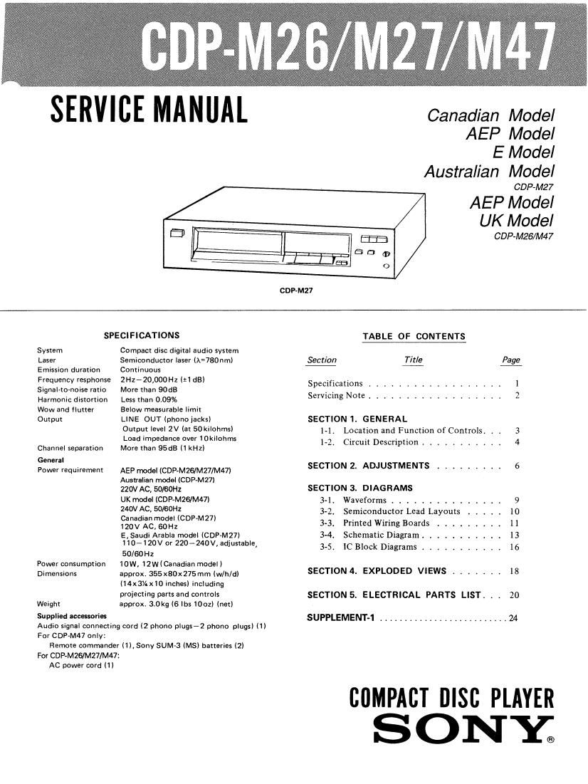
Sony CDP M47 Service Manual
This is the 18 pages manual for Sony CDP M47 Service Manual.
Read or download the pdf for free. If you want to contribute, please upload pdfs to audioservicemanuals.wetransfer.com.
Extracted text from Sony CDP M47 Service Manual (Ocr-read)
Page 1
SERVIE MANUAL
Canadian Model
AEP Model
E Model
Australian Model
CDP-M27
AEP Model
UK Model
ED [I E53 CDP-M26/M47
(L: - m E D G?
l___uas O
COP-M27
SPECIFICATIONS TABLE OF CONTENTS
System Compact disc digital audio system
Laser Semiconductor laser (A=780nml Section Title Page
Emission duration Continuous
Frequency resphonse 2Hz-20,000HZ (:1 dB) Specifications ............... l
SIgnal-to-noise ratio More than 90dB , , 2
Harmonic distortion Less than 0.09% Servxcmg Note """""""""
Wow and flutter Below measurable limit
Output LINE OUT (phonoiacksl SECTION 1. GENERAL
Output level 2V (3 50ki|°hmsl 1-1. Location and Function of Controls. . . 3
Load impedance over 10kilohms _ . . , .
Channel separation More than 95dB (1 kHz) I 2' Circuit Dascrlption ......... 4
General
Power requirement AEP model (CDP-MZG/M27/M47) SECTION 2. ADJUSTMENTS ......... 6
Australian model (GDP-M27)
220V AC, 50/60H2 SECTION 3. DIAGRAMS
UK model (CDP-MZG/M47) 3-1. Waveforms ............... 9
gov AC' {IO/BOWCDP M27) 3-2. Semiconductor Lead Layouts ..... 10
123::3Tggfiz ' 33. Printed Wiring Boards ......... l 1
E, Saudi Arabla model (CDP-M27) 3-4. Schematic Diagram . . . l3
110-120V or 220~240V4 adjustable, 3_5 IC Block Diagrams 16
50/60Hz """""
Power consumption 10W, 12W(Canadian model)
Dimensions approxi 355x80x275mm (w/h/d) SECTION 4 EXPLODED VIEWS 18
(14x3/. x10 inches) including
projecting Parts and controls SECTION 5. ELECTRICAL PARTS LIST. . . 20
Weight approxi 30kg (6 lbs 1002) (netl
Supplied accmories SUPPLEMENT-1 .......................... 24
Audio signal connecting cord (2 phono plugs-2 phono plugs) (1)
For CDP-M47 only
Remote commander (1), Sony SUM»3 (MS) batteries (2)
For CDP-MZS/MZ7/M47:
AC power cord
(1)
BflMPABT msc PLAYER
SONY;
Page 2
CDP-M26/M27/M47
SAFETY-RELATED COMPONENT WARNINGI!
COMPONENTS IDENTIFIED BV MARK A OR DOTTED
LINE WITH MARK A ON THE SCHEMATIC DIAGRAMS
AND IN THE PARTS LIST ARE CRITICAL TO SAFE
OPERATION. REPLACE THESE COMPONENTS WITH
SONY PARTS WHOSE PART NUMBERS APPEAR AS
SHOWN IN THIS MANUAL OR IN SUPPLEMENTS PUB-
LISHED BY SONY.
ATTENTION AU COMPOSANT AYANT RAPPORT
A LA SECURITE!
LEs COMPOSANTS IDENTIFIES PAR UNE MARGUE A
suR LES DIAGRAMMES SCHEMATIQUES ET LA LISTE
DES PIECES som camouEs POUR LA sEcURirE
DE FONCTIONNEMENT. NE REMPLACER CES COM-
POSANTS our: PAR DES PIECES SONY DONT LES
NUMERos SONT DONNEs DANS CE MANUEL ou
DANS LEs SUPPLEMENTS PUBLIES PAR SONV.
PROTECTION OF EYES FROM LASER BEAM DURING SERVICING
This set employs a laser. Therefore, be sure to fol-
low carefully the instructions below when servicing.
CAUTION
Use of controls or adjustments or performance
of procedures other than those specified herein
may result in hazardous radiation exposure.
NOTES ON HANDLING THE OPTICAL PICK-
UP BLOCK OR BASE UNIT
The 1aser diode in the optical pick-up block may
suffer electrostatic breakdown because of the poten-
tial difference generated by the charged electrostatic
load, etc on clothing and the human body.
During repair, pay attention to electrostatic break-
down and also use the procedure in the printed
matter which is included in the repair parts.
The flexible board is easily damaged and should be
handled with care.
1. Laser Diode Properties
0 Material: GaAlAs
O Wavelength: 780 nm
0 Emission Duration: continuous
0 Laser Output: max. 446 uW*
* This output is the value measured at a distance of
about 200 mm from the objective lens surface on
the Optical Pick-up Block.
2 During service, do not take the Optical Pick-up
Block apart, and do not adjust the APC circuit.
If there is a breakdown in the APC circuit (includ-
ing laser diode), replace the entire Optiocal Pick-
up Block (including APC borad).