Sony a 92 gx 18 c 820 service manual

This is the 38 pages manual for sony a 92 gx 18 c 820 service manual.
Read or download the pdf for free. If you want to contribute, please upload pdfs to audioservicemanuals.wetransfer.com.

Page: 1 / 38
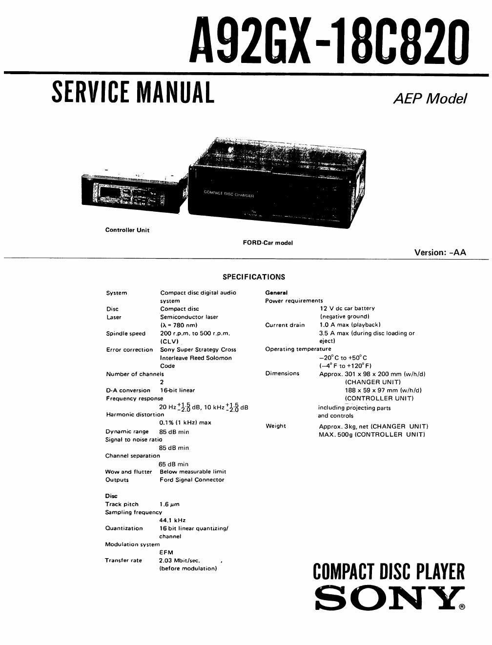
sony a 92 gx 18 c 820 service manual

Extracted text from sony a 92 gx 18 c 820 service manual (Ocr-read)


Page 1

AQZGX-lBBBZU

SERVICE MANUAL

Controller Unit

AEP Model

FORD-Car model

Version: -AA

SPECIFICATIONS

System Compacr disc digital audio
system

Disc Compact disc

Laser Semiconductor laser
(X = 780 nrnl

Spindle speed 200 r.p.mt to 500 r.p.m.
lCLVl

Error correction Sony Super Strategy Cross
Interleave Reed Solomon
Code

Number of channels
2

D-A conversion 16-bit linear

Frequency response
20 Hz 31.3 dB, 10 kHz 38 dB

Harmonic distortion '
0.1% ll kHz) max

Dynamic range 85 dB min

Signal to norse ratio

85 dB min
Channel separation
65 dB min
Wow and flutter Below measurable limit
Outputs Ford Signal Connector
Disc
Track pitch 1.5 pm
Sampling frequency
44.! kHz
Quantization 16 bit linear quantaing/
channel
Modulation system
EFM
Transfer rate 2113 Mon/sect .

lbelore modulation)

Gen-rel
Power requirements
12 V dc car battery
(negative ground]
Current drain 1.0 A max (playback)
35 A max (during disc loading or
elect)
Operating temperature
-2o°c to +50°c
l-4°F to +120°Fl
Dimensions Approx, 301 x 98 x 200 mm lw/h/d)
(CHANGER UNIT)
188 x 59 x 97 mm (w/h/d)
(CONTROLLER UNIT)
including projecting parts
and controls

Weight Approx. 3kg, net (CHANGER UNIT)
MAX. 5009 (CONTROLLER UNIT)

CflMPACT DISC PLAYER
SONY;

Page 2

A926X-1 80820

TABLE OF CONTENTS

Title Page

Section

Specifications -------

SECTION 1. SERVICING NOTES
Notes on Handling the OpticaI Pick-up

Block or Base Unit ................................. 2

Protection of Eyes from Laser Beam.

during Servicing ................................... 3
SECTION 2- DISASSEMBLV ........................ 4
SECTION 3. IC PIN DESCRIPTION

Port Expander ICEOS CX'ISSI Pin Functions ----------- 5

Main Control ICSOS uPD7508II Pin Functions ---------- 6

System Control 16901 pPD75308 Pin Functions -------- 8

SECTION 4. MECHANICAL ADJUSTMENTS
Large Elevator Gear Position
(Location 10.5) Adjustment -----------

Homing Adjustment ....................

SECTION 5. ELECTRICAL ADJUSTMENTS

Focus Offset Adjustment ................... [2
Tracking Offset Adjustment . . . . . . . . . . . .1 . . . . 12
Tracking Gain Adjustment ~~~~~~


----------- 13
Focus Gain Adjustment -------- ..
PLL Freerun Frequency Adjustment ----------------

SECTION 6. DIAGRAMS
6-1. Block Diagram ................................ 15
62. Printed Wiring Boards (Controller Section) 18
6-3. Schematic Diagram (Controller Section) """"
6-4. Schematic Diagram (Changer Section) -
6-5. Printed Wiring Boards (Changer Section) ..
6-6. Printed Wiring Boards (RF Section) ----------- 34

mprI-o

67. IC Block Diagrams ....................... 37
5-3. wavemes ............................... 39
6-9. Semiconductor Lead Layouts ------------------- 40
SECTION 7. EXPLODED VIEWS """""""""""""" 41
SECTION 8. ELECTRICAL PARTS LIST ~~~~~~~~ 4B

SAFETY-RELATED COMPONENT WARNING

COMPONENTS IDENTIFIED BV MARK A 0R DOTTED
LINE WITH MARK A ON THE SCHEMATIC DIAGRAMS
AND IN THE PARTS LIST ARE CRITICAL TO SAFE
OPERATION. REPLACE THESE COMPONENTS WITH
SONY PARTS WHOSE PART NUMBERS APPEAR AS
SHOWN IN THIS MANUAL OR IN SUPPLEMENTS PUB-
LISHED BY SONV.

SECTION 1
SERVICING NOTES

NOTES ON HANDLING THE OPTICAL PICK-
UP BLOCK OR BASE UNIT

The laser diode in the optical pick-up block may
suffer electrostatic breakdown because of the poten-
tial difference generated by the charged electrostatic
load, etc. on clothing and the human body.

During repair, pay attention to electrostatic break-
down and also use the procedure in the printed
matter which is included in the repair parts.

The flexible board is easily damaged and should be
handled with care.