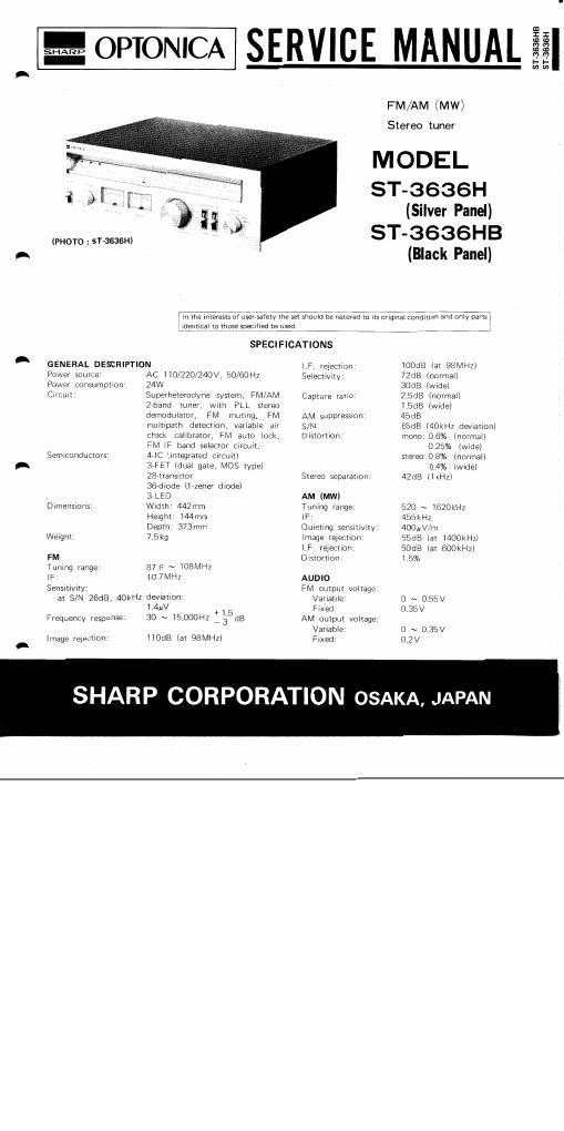
Sharp st 3636 h service manual
This is the 38 pages manual for sharp st 3636 h service manual.
Read or download the pdf for free. If you want to contribute, please upload pdfs to audioservicemanuals.wetransfer.com.
Extracted text from sharp st 3636 h service manual (Ocr-read)
Page 1
%OPTONICA SERVICE MANUAL
FM/AM (MW)
Stereo tuner
MODEL
ST-3636H
(Silver Panel)
(PHOTO : ST-3636H) ST_3636HB
A (Black Panel)
ST- 3636 H B
ST- 3636 H
Iii-tile interests of usersaiety the set shou Id be restored to its original condition and only partgi
identical to those specified be used. I
SPECIFICATIONS
A GENERAL DESCRIPTION (F. rejection: iOOdB (at 98MHZ)
Power source: AC ll0/220/24OV, 50/60H2 Selectivitv' 72dB (normal)
Power consumption: 24W 30dB (wide)
Circuit: Superheterodyne system, FlVl/AM Capture ratio: 2:5dl3 (normal)
Zrband tuner, with PLL stereo 1.5dB (wide)
demodulator, FM muting, FM AM suppression: 45dB
multipath detection, variable air S/N: 65:38 (40kHz deviation)
check calibrator, FM auto lock, Distortion: mono:0,6% (normal)
FM IF band selector circuit. 0.25% (wide)
Semiconductors: 4-IC (integrated circuit) stere0'0.8% (normal)
A 37FET (dual gate, MOS type) 0.4% (Wide)
28-transistor Stereo separation: 42dB (lkHz)
367diode (lazener diode)
37LED AM (MW)
Dimensions: Width: 442mm Tuning range: 520 ~ iGZOkHz
Height: 144mm IF' 455kHz
Depth: 373mm Quieting sensitivity: 400uV/m
Weight: 7.5kg Image rejection: 55d8 (at l400kHzI
(F. rejection: 50dB (at 600kHzl
FM Distortion: i.5%
Tuning range: 87.6 ~ 108MHz
lF: iO.7I\/IH2 AUDIO
Sensitivity: FM output voltage.
at S/N ZGdB: 40kHz deviation: Variable: 0 ~ 0,55V
1.4uV +1 5 Fixed: 0,35V
Frequency response: 30 ~ l5,000Hz M3; dB AM output voltage:
Variable 0 ~ 0.35V
Image reiection: l10dB (at 98MHZ) Fixed: 02v
SHARP CORPORAT ON OSAKA, JAPAN
Page 2
VOLTAGE SELECTlON
Check the preset voltage before connecting the mains plug
to a mains outlet. If the setting is different from your local
supply mains voltage, the selector must be reset as follows.
Rotate the voltage selector by using a screw driver so that
your local voltage number can be seen.
Prior to removing the chassis, be sure to
draw the power supply plug from a wall
outlet. Then, proceed with the removal
work in the following order after disconnect-
ing all of the connection cords at the rear
of the set.
H To remove the cabinet:
Remove 12 screws ® retaining the
cabinet (6 screws each for the right
and left sides), then the cabinet can
be detached.
2) To remove the bottom board:
Turn over the set and remove 8 screws
(2 retaining the bottom board, then
the bottom board can be detached.
3) To remove the front panel'
ll) Use a hexagonal wrench (1.4mm)
to loosen the screw retaining the
tuning knob (3) at the front panel,
and pull out the tuning knob.
(2) Pull out the remaining knobs @
l5 knobs).
(3) Finally remove 4 screws 6)) retain»
ing the front panel, then the iront
panel can be detached,
L Figure 'l
DISASSEMB LY
Figure 2 DISASSEMB LY