Sharp cp g 5000 service manual

This is the 131 pages manual for sharp cp g 5000 service manual.
Read or download the pdf for free. If you want to contribute, please upload pdfs to audioservicemanuals.wetransfer.com.

Page: 1 / 131
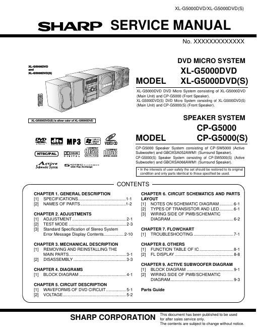
sharp cp g 5000 service manual

Extracted text from sharp cp g 5000 service manual (Ocr-read)


Page 1

XL-GSOOODVD/XL-GSOOODVD(S)

SHARP SERVICE MANUAL

XL-GSOODDVD
and
XL-GSOOODVD(S)


Q

.u

G)

I

wuss mumuu "'3

un- @DSB

VIDEO CD

:nmnm

cum-ct

NTSC/PAL D . a . Q . L
Active D . s c CCCCCCC
SubwooIer System m" "1 5"9

CHAPTER 1. GENERAL DESCRIPTION
[1] SPECIFICATIONS .......

N0.XXXXXXXXXXXXX

DVD MICRO SYSTEM
XL-G5000DVD
MODEL XL-G5000DVD(S)

XL-GSOOODVD DVD Micro System consisting of XL-GSOOODVD
(Main Unit) and CP-GSOOO (Front Speaker).

XL-GSOOODVD(S) DVD Micro System consisting of XL-G5000DVD(S)
(Main Unit) and CP-G5000(S) (Front Speaker).

SPEAKER SYSTEM
CP-G5000
MODEL CP-G5000(S)

CONTENTS

CRGSOOO Speaker System consisting of CP-SW5000 (Active
Subwoofer) and GBOXSA052AWM1 (Surround Speaker).
CP-G5000(S) Speaker System consisting of CP-SW5000(S) (Active
Subwoofer) and GBOXSAOBGAWMI (Surround Speaker).

- In the interests of user-satety the set should be restored to its original
condition and only parts identical to those specified be used.

\

CHAPTER 6. CIRCUIT SCHEMATICS AND PARTS
LAYOUT

[2] NAMES OF PARTS ..... [1] NOTES ON SCHEMATIC DIAGRAM...
[2] TYPES OF TRANSISTOR AND LED....

CHAPTER 2. ADJUSTMENTS [3] WIRING SIDE OF PWB/SCHEMATIC
[1] ADJUSTMENT.. DIAGRAM ...................................................... 6-2
[2] TEST MODE .....
[3] Standard Specification of Stereo System CHAPTER 7. FLOWCHART

Error Message Display Contents ................. 2-10 [I] TROUBLESHOOTING .................................. 7»1
CHAPTER 3. MECHANICAL DESCRIPTION CHAPTER 8. OTHERS
[1] REMOVING AND REINSTALLING THE [1] FUNCTION TABLE OF IC ..... 8»1

MAIN PARTS ........ [2] FL DISPLAY .............................. 8-8
[2] DISASSEMBLY

CHAPTER 9. ACTIVE SUBWOOFER DIAGRAM
CHAPTER 4. DIAGRAMS [1] BLOCK DIAGRAM ........................................ 91
[1] BLOCK DIAGRAM ........................................ 4-1 [2] WIRING SIDE OF PWB/SCHEMATIC
DIAGRAM ...................................................... 9-3
CHAPTER 5. CIRCUIT DESCRIPTION
[1] WAVEFORMS OF DVD CIRCUIT... Parts Guide
\ [2] VOLTAGE ........................................ /
SHARP CORPORATION This document has been published to be used
for after sales servrce only.

The contents are subject to change without notice.

Page 2

XL-G5000DVD/XL-G5000DVD(S)

SAFETY PRECAUTION FOR SERVICE MANUAL

Precaution to be taken when replacing and servicing the Laser Pickup.
The AEL (Accessible Emission Level) of Laser Power Output for this model is specified to be lower than Class 1 Requirements.
However, the following precautions must be observed during servicing to protect your eyes against exposure to the Laser beam.

1. When the cabinet has been removed, the power is turned on without a compact disc, and the Pickup is on a position outer than the
lead-in position, the Laser will light for several seconds to detect a disc. Do not look into the Pickup Lens.

. The Laser Power Output of the Pickup inside the unit and replacement service parts have already been adjusted prior to shipping.

. No adjustment to the Laser Power should be attempted when replacing or servicing the Pickup.

. Under no circumstances look directly into the Pickup Lens at any time.

. CAUTION - Use of controls or adjustments, or performance of procedures other than those specified herein may result in
hazardous radiation exposure.

01-wa

VOLTAGE SELECTION

Before operating the unit on mains, check the preset voltage. If the voltage is different from your local voltage, adjust the voltage

as follows.
Turn the selector with a screwdriver until the appropriate voltage number appears in the window (110V,127V,220V or 230V -
240V AC).
AC POWER SUPPLY CORD AND AC PLUG ADAPTOR
QACCA0008AWOO QPLGAOOOSAWZZ QPLGA0004AWZZ
D
QACCE0015AWOO