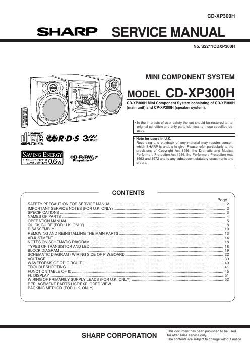
Sharp cd xp 300 h service manual
This is the 43 pages manual for sharp cd xp 300 h service manual.
Read or download the pdf for free. If you want to contribute, please upload pdfs to audioservicemanuals.wetransfer.com.
Extracted text from sharp cd xp 300 h service manual (Ocr-read)
Page 1
CD-XP300H
SHARP SERVICE MANUAL
No. $2211CDXP300H
7% , . MINI COMPONENT SYSTEM
,(\_'f, . f '( MODEL CD-XP300H
CD-XP300H Mini Component System consisting of CD-XP300H
(main unit) and CP-XP3DOH (speaker system).
- In the interests of user-safety the set should be restored to its
original condition and only parts identical to those specified be
used.
COMPACT
filfl§@ @R'D's 6€€ - Note let users in U.K. . .
mam, AUDIO Recording and playback of any material may require consent
which SHARP is unable to give. Please refer particularly to the
provisions of Copyright Act 1956, the Dramatic and Musical
SAVING ENERG CD-R/RW Performers Protection Act 1956, the Performers Protection Acts
STAN m pownz O 6 Pla able/ 1963 and 1972 and to any subsequent statutory enactments and
Y
CONSUMPTION . W orders.
/- CONTENTS %
SAFETY PRECAUTION FOR SERVICE MANUAL
IMPORTANT SERVICE NOTES (FOR U.K. ONLY) ..
SPECIFICATIONS .....
NAMES OF PARTS
OPERATION MANUAL.
QUICK GUIDE (FOR U.K. ONLY
DISASSEMBLY...
REMOVING AND
ADJUSTMENT ...................................
NOTES ON SCHEMATIC DIAGRAM
TYPES OF TRANSISTOR AND LED.
BLOCK DIAGRAM .............................
SCHEMATIC DIAGRAM / WIRING SIDE OF P.W.BOARD.
VOLTAGE ...................................
WAVEFORMS OF CD CIRCUIT.
TROUBLESHOOTING ......
FUNCTION TABLE OF IC.
FL DISPLAY ......................
WIRING OF PRIMARILY SUPPLY LEADS (FOR U.K. ONLY) ..
REPLACEMENT PARTS LIST/EXPLODED VIEW
PACKING METHOD (FOR U.K. ONLY)
This document has been published to be used
SHARP CORPORATION for after sales service only.
The contents are subject to change without notice.
Page 2
CD-XP300H
DISASSEMBLY
Caution on Disassembly
Follow the below-mentioned notes when disassembling
the unit and reassembling it, to keep it safe and ensure
excellent performance:
1. Take cassette tape and compact disc out of the unit.
2. Be sure to remove the power supply plug from the wall
outlet before starting to disassemble the unit.
3. Take off nylon bands or wire holders where they need to
be removed when disassembling the unit. Afterservicing
the unit. be sure to rearrange the leads where they were
before disassembling.
4. Take sufficient care on static electricity of integrated
circuits and other circuits when servicing.
XP300H
STEP REMOVAL PROCEDURE FIGURE
1 Top Cabinet 1. Screw. . (A1) x4 10-1
2 Side Panel 1. Screw. . (Bt) x8 10-1
(Left/Right)
3 CD Tray Cover/ 1. Turn on the power supply, 10-2
CD Player Unit open the disc tray, take out
the CD tray cover, and close.
(Note 1)
2. Screw. . (C1) x1
3. Hook . (
4. Hook . (
5. Socke .
4 Rear Panel with 1. Screw . . 10-2
Fan Motor 2. Socket . (D2)
5 Main PWB/ 1. Screw. . (E1) X4 10211-1
RDS PWB 2. Socket . (E2) X3 11-1
3. Flat Ca . . (E3) x1
4. Flat Wire.... . (E4) x1
6 Front Panel 1. Screw . ..( 11-1
2. Hook
3. Socket ..
7 Display PWB 1. Screw ..... ( 1) x12 11-2
2. Flat Cable . . (G2) x1
8 Tape Mechanism 1. Open the cassette holder. 11-2
2. Screw ...................... (H1) x5
9 Headphones PWB 1. Screw. .. (J1) x1 11-2
10 Turntable 1. Hook . (K1) x2 11-3
2. Cover . . (K2) x1
11 Loading Tray 1. Turn fully the lock lever ln the 10-3
arrow direction.
2. Push the loading tray backward 11-4
to engage the claw with the
groove and remove it in the
direction of the arrow... (L1) x6
12 CD Servo PWB 1.Screw. .(M1)x2 11-5
(Note 2) 2. Hook .(M2) x1
3. Socket .(M3) x4
13 CD Mechanism 1. Hook . (N1) x2 11-6
2. Hook . (N2) x2
Note 1: How to open the changer manually. (Fig. 10-3)
1. In this state, turn fully the lock lever in the arrow direction through
the hole on the loading tray bottom.
2. After that, push forward the loading tray.
Note 2:
1. After removing the connector for the optical pickup from the
connector, wrapthe conductive aluminiumfoil around thefrontend
of the connector so as to protect the optical pickup from electro-
static damage.
Note 3:
1. Be careful not to break the claw of the CD mechanism.
2. When fining back the cam gear assembly, let it lock by front
movement.
_10_
(B1)x2
o3x10mm
CD-XP300H
Top Cabinet
(A1)x2 4%
a3x12mm
Side Panel
(Right)
(B1)x4
o3x10mm
Lock Lever
CD Player Unit
(Bottom View)
/
(D1)x7
ontOmm
(E1)x1
on10mm
0
(Left)
/31) x 2
133 x 10mm
(D)x1 o3x 10mm
o3x10mm
Figure 10-2
w
\@
Figure 10-3