Sharp cd mps 1000

This is the 101 pages manual for sharp cd mps 1000.
Read or download the pdf for free. If you want to contribute, please upload pdfs to audioservicemanuals.wetransfer.com.

Page: 1 / 101
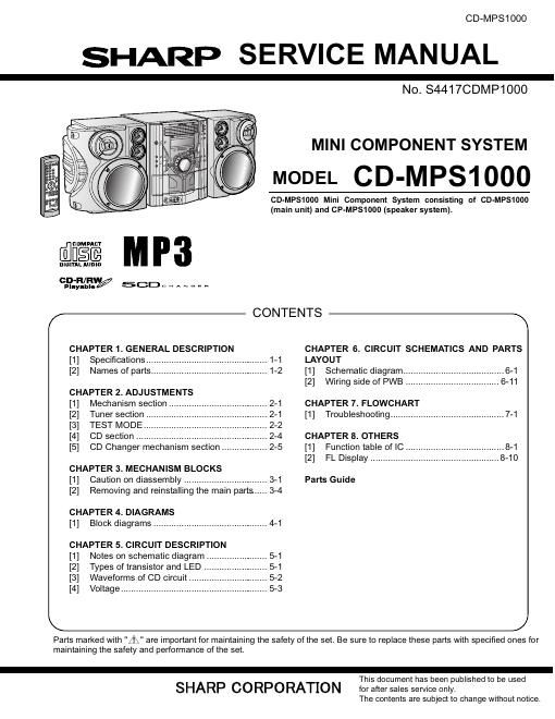
sharp cd mps 1000

Extracted text from sharp cd mps 1000 (Ocr-read)


Page 1

CD-MPS1000

SHARP SERVICE MANUAL

N0. S441 YCDMPIOOO

MINI COMPONENT SYSTEM

MODEL CD-MPS1000

CD-MPS1000 Mini Component System consisting of CD-MPS1000
(main unit) and CP-MPS1000 (speaker system).

COM PACT

5E

DIGIYAL Aumn

cfifiéfiml/ SCDnHANn;n

CONTENTS
(f \\

CHAPTER 1. GENERAL DESCRIPTION
[1] Specifications...
[2] Names of parts....

CHAPTER 2. ADJUSTMENTS
[1] Mechanism section
[2] Tuner section
[3] TEST MODE
[4] CD section
[5] CD Changer mec anism sec Ion


CHAPTER 3. MECHANISM BLOCKS
[1] Caution on diassembly ................................. 3-1
[2] Removing and reinstalling the main parts ..... 3-4

CHAPTER 4. DIAGRAMS
[1] Block diagrams ............................................. 4-1

CHAPTER 5. CIRCUIT DESCRIPTION
[1] Notes on schematic diagram ......
[2] Types of transistor and LED
[3] Waveforms of CD circuit ..
[4] Voltage .................................


K.

Parts marked with "A, " are important for maintaining the safety of the set. Be sure to replace these parts with specified ones for

maintaining the safety and performance of the set.

SHARP CORPORATION

CHAPTER 6. CIRCUIT SCHEMATICS AND PARTS
LAYOUT

[1] Schematic diagram ............. 6-1
[2] Wiring side of PWB ...... 6-11
CHAPTER 7. FLOWCHART

[1] Troubleshooting ............................................. 7-1
CHAPTER 8. OTHERS

[1] Function table of IC ........ 8-1
[2] FL Display ........................ 8-10

Parts Guide

./

This document has been published to be used
for after sales service only.

The contents are subject to change without notice.

Page 2

CD-MPSl 000
IMPORTANT SERVICE NOTES

BEFORE RETURNING THE AUDIO PRODUCT

BEFORE RETURNING THE AUDIO PRODUCT

(Fire & Shock Hazard)

Before returning the audio product to the user, perform the following

safety checks.

. Inspect all lead dress to make certain that leads are not pinched or
that hardware is not lodged between the chassis and other metal
parts in the audio product.

2. Inspect all protective devices such as insulating materials, cabinet,
terminal board, adjustment and compartment covers or shields,
mechanical insulators etc.

3. To be sure that no shock hazard exists, check for leakage current in

the following manner.

Plug the AC line cord directly into a 120 volt AC outlet.

Using two clip leads, connect a 1.5 kohm, 10 watt resistor paralleled

by a 0.15 pF capacitor in series with all exposed metal cabinet parts

and a known earth ground, such as conduit or electrical ground con-
nected to earth ground.

Use a VTVM or VOM with 1000 ohm per volt, or higher, sensitivity to

measure the AC voltage drop across the resistor (See diagram).

Connect the resistor connection to all exposed metal parts having a

return path to the chassis (antenna, metal cabinet, screw heads,

knobs and control shafts, escutcheon, etc.) and measure the AC
voltage drop across the resistor.

.

.

All check must be repeated with the AC line cord plug connection
reversed.

Any reading of 0.3 volt RMS (this corresponds to 0.2 milliamp. AC.) or
more is excessive and indicates a potential shock hazard which must
be corrected before returning the audio product to the owner.

9%

VTVM
'0 AC SCALE 0'

1.5 kohms
10 W

0.15 mF

TEST PROBE CONNECT TO

KNOWN EARTH
GROUND

TO EXPOSED
METAL PARTS