Sharp cd dk 2500 w service manual

This is the 176 pages manual for sharp cd dk 2500 w service manual.
Read or download the pdf for free. If you want to contribute, please upload pdfs to audioservicemanuals.wetransfer.com.

Page: 1 / 176
sharp cd dk 2500 w service manual

Extracted text from sharp cd dk 2500 w service manual (Ocr-read)


Page 1

CD-DP2500W/DK2500W

SHARP SERVICE MANUAL

No. S4034CDDP2500

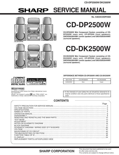
CD-DP2500W

CD-DP2500W Mini Component System consisting of CD-
DP2500W (main unit), CP-DP2500 (front speakers),

fl GBOXSOO38AWM1 (centre speaker) and GBOXSOOSQAWM1
: (surround speakers).
C D- D K2 5 00W
CD-DK2500W Mini Component System consisting of CD-
DK2500W (main unit), CP-DP2500 (front speakers),
GBOX50038AWM1 (centre speaker) and GBOXSOOSQAWM1
EH (surround speakers).
.. ¥A
CD-DK2500W
DIFFERENCE BETWEEN CD-DPZSOOW AND CD-DK2500W
COMPACT
D§[E SAVING ENERGY SECTION CDVDPZSOOW CDVDKZSOOW
STAND-BY [:0ng KARAOKE Non Used
DIGITAL AUDIO CONSUMPWN 0 8w
D_
p R o . L o a I c
Inflganégfififiiflm license Imm Dmby Laboratores Lice - In the interests of user-safety the set should be restored to its
DOLEy, (he do'ubleo symbm DC] and "FRO LOGIC" are original condition and only parts identical to those specified be
trademarks of Dolby Laboratories Licensing Corporation. used.

/- CONTENTS

SAFETY PRECAUTION FOR SERVICE MANUAL
VOLTAGE SELECTION.
SPECIFICATIONS .....
NAMES OF PARTS
OPERATION MANUAL ..
DISASSEMBLY
REMOVING AND
TEST MODE
ADJUSTMENT .
NOTES ON SCHEMATIC DIAGRAM .
BLOCK DIAGRAM .............................
SCHEMATIC DIAGRAM / WIRING SIDE OF P.W.BOARD ..
VOLTAGE ....................................
WAVEFORMS OF CD CIRCUIT ..
TROUBLESHOOTING (CD SECTION) .
FUNCTION TABLE OF IC.
FL DISPLAY ......................
REPLACEMENT PARTS LIST/EXPLODED VIEW

This document has been published to be used

SHARP CORPORATION for after sales service only.

The contents are subject to change without notice.

Page 2

CD-DP2500W/DK2500W

SAFETY PRECAUTION FOR
SERVICE MANUAL

CAUTION

CLASS I LASER PRODUCT

APPAREIL A LASEII DE BLASSE I
PRODUCTD LASER l]E ELISE l

Precaution to be taken when replacing and servicing the
Laser Pickup.

The AEL (Accessible Emission Level) of Laser Power Output 0 This Mini Component System is classified as a CLASS 1

forthis model is specified to be lowerthan Class | Requirements. LASER product.

However, the following precautions must be observed during 0 The CLASS1 LASER PRODUCT label is located on the
servicing to protect your eyes against exposure to the Laser rear COVer- _

beam 0 Use of controls, adjustments or performance of proce-

dures other than those specified herein may result in haz-

. . d d' t' .
(1) When the cablnet has been removed, the power ls turned a nus re la Ion eXposure

0 WIIhOUI a compact disc; and the PICKUP LS on a position As the laser beam used in this compact disc player is
outerthanthelead-ln posttlon,the LaserWIll llghtforseveral harmful to the eyes, do not attempt to disassemble the
seconds to detect a disc. Do not look into the Pickup Lens. cabinet. Refer servicing to qualified personnel only.

(2) The Laser Power Output of the Pickup inside the unit and

. , , Laser Diode Properties
replacement serwce parts have already been adjusted prlor

Material: GaAlAs

to shipping. Wavelength: 780 nm
(3) No adjustment to the Laser Power should be attempted Emission Duration: continuous
when replacing or servicing the Pickup. Laser Output: max. 0.6 mW

(4) Under no circumstances look directly into the Pickup Lens
at any time.

(5) CAUTION - Use of controls or adjustments, or performance
of procedures other than those specified herein may result
in hazardous radiation exposure.

CAUmW AnsmLe Em mim» Mia om Di) m fink: im
mu OR um immy mi ochL nml 'ML\1S
twmuwm is i wmsmAlAM m iii M iii in imam mm
ii i\ i mum u ii mm ii iiiui i.» mm i M Miami
Am mumps memm m we

mm im \D mm mmn .

MA iii.i it iiimii
mu H mm USU omSKT

mum: um» um m mum
m :2 nwm \er mica hsmulnm

Illustration:CD-DP2500W

VOLTAGE SELECTION

The voltage selector is located on the AC voltage selector box. If adjustment is necessary. ensure to remove plug of AC cord from
AC socket and use a screwdriver in order to turn the selector in eitherdirection. The correctvoltagefigure is displayed in the window
below to the adjustment screw.

QACCBOOOGAWOO QACCAOOOSAWOO

D

QACCEOO10AWOO

QACCJ0007AW00

QFLGAOOO3AWZZ QPLGA0004AWZZ

Figure 2 POWER SUPPLY CORD
_ 2 _