Scott 340B Service Bulletin Early

This is the 7 pages manual for Scott 340B Service Bulletin Early.
Read or download the pdf for free. If you want to contribute, please mail your pdfs to info@audioservicemanuals.com.

Page: 1 / 7
left right
Scott 340B Service Bulletin Early

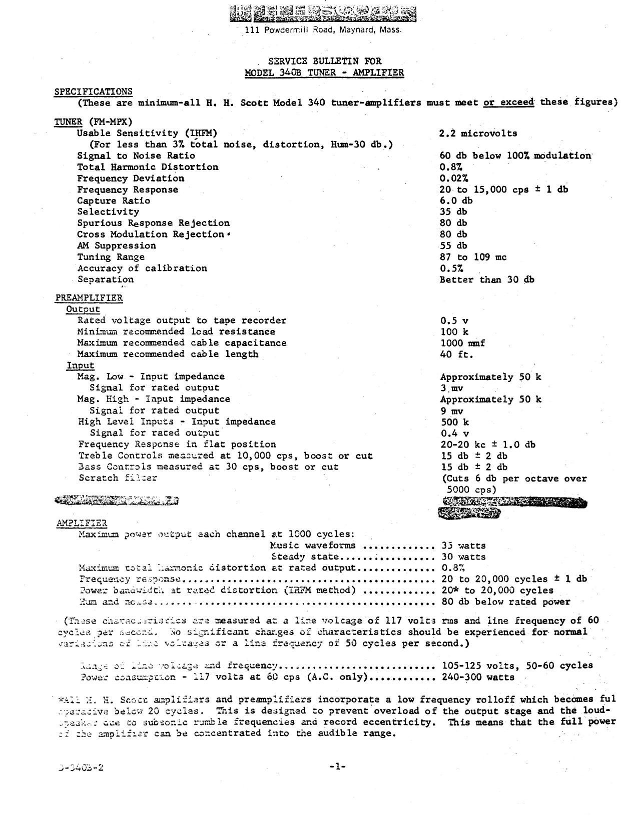
Extracted text from Scott 340B Service Bulletin Early (Ocr-read)


Page 1

' 111 Powdermlll Road, Maynard. Mass.

. SERVICE BULIETIN FOR
MODEL 3403 TUNER - AMPLIFIER

SPECIFXCATIONS »
(These are minimum-all 1-1. E. Scott Model 3100 tuner-amplifiers must meet or exceed these figures}

TUNER (FM-MPX)

Usab 1e Sensitivity (IHFH)

(For less than 37. total noise, distortion, Hum-30 (1b,)

Signal to Noise Ratio
Total Harmonic Distortion

2.2 microvolts

so db below 1001 modulation
0.87.

Frequency Deviation ' . 0.02%

Frequency Response . 20 to 15,000 cps i 1 db

Capture Ratio 6.0 db

Selectivity 35 db

Spurious Response Rejection 80 db

Cross Modulation Rejection 80 db

AM Suppression 55 db

Tuning Range 87 to 109 me

Accuracy of calibration 0.51

Separation Better than 30 db

PREAMPLIFIER
Output .

Rated voltage output to tape recorder 0.5 v

Minimum recommended load resistance 100 k

Maximum recommended cable capacitance 1000 mmf

Maximum recommended cable length 40 ft.

Input '

Mag. Low - Input impedance Approximately 50 k
Signal for rated output 3,mv

Mag. High - input impedance Approximately 50 k
Signal for rated output 9 mv '

High Level Inputs - Input impedance 500 1:
Signal for rated output 0.4 v

Frequency Response in flat position 20-20 kc i 1.0 db

Treble Controls measured at 10,000 cps, boost or cut 15 db t 2 db

Bass Controls measured at 30 cps, boost or cut 15 db 1' 2 db

Scratch fetter (Cuts 6 db per octave over

5000 cps)

AMELIFIE.
Maximum power output each channel at 1000 cycles:

Music waveforms ............. 33 watts
Steady state...... .......... 30 watts
:ic distortion at rated output.............. 0. X
.. 20 to 20,000 cycles 1 1 db
.. 20* to 20,000 cycles
.. 80 db below rated power

lilacimum two.
Ftequeucy re unse......................................
Iowe: ban t at rated distortion (IEFM method) ......

31m and 10.33......................


v...............--o

measured at: a lire voltage of 117 volts ms and line frequency of 60
es of characteristics should be experienced for» normal
uency of 50 cycles per second.)

:1 and frequency............................ 105-125 volts, 50-60 cycles
.117 volts at '60 cps (A.C. only)............ 240-300 watts

:1: 33an flats and presmplifiers incorporate a low frequency rolloff which becomes ful
below 20 les. This is designed to prevent overload of the output stage and the loud-

r... to subs rumble frequencies and record eccentricity. This means that the full power
_- -..=: emplc- k. can be concentrated into the audible range.

1-3402-2 -1-

Page 2

TUNER SECTION
GENERAL SERVICE NOTES

Service, other than replacement of either pilot lights or vacuum tubes, is usually not
required. If the tuner is not operating properly, all external connections should be checked
to-make sure that the difficulty is in the tuner. Generally, it is advisable to replace the
tuner with a tape recorder or similar device to check out the amplifier performance. _If the
difficulty appears to be located in the tuner, the level control should be 'first checked to
insure that it is rotated away from its extreme counter-clockwise position. Then, the vacuum
tubes should be checked by replacing them with new ones, one by one. The tubes should be tight
in their sockets and provided with shields where applicable. 'l'ube defects frequently do not
show up in a tube tester. Only operation in the tuner will insure the proper working of a
vacuum tube. In replacing tubes, if possible, use exact replacement tubes, available from
H. [-1. Scott or any authorized warranty service station. Other tubes will work, but only exact
replacment tubes can give the full performance that the tuner is capable of.

Pilot Light Replacement:

l. Rmove the sheet metal screws on top and on each end of the control shield which covers
the top, front section of the unit and carefully lift the shield up and backwards.
There are wires connected to the shield, so do not pull it too far.

2. Remove the dial indicator lights by squeezing in on the spring clips and pulling back-
wards. The replacements should be bayonet type #47 bulbs. Be sure to remove the
"beam shields" from the old bulbs and re-install them on the new bulbs.

3. If the meter bulb, located on the control shield, needs replacement, it will be neces-
sary to contact the factory for the replacement. When ordering, specify number
VPL-47-Blue.

4. Re-install the control shield in the same manner as it was removed and replace all six
screws.

Dial Cord Replacement:
1. If the dial cord should break, a replacement may be ordered tron our Parts Department
by specifying number ADC- 1. If a new dial cord spring is required, number ASP-d
should be specified.

2. Remove the control shield as outlined in step number 1 above. Remove the broken dial
cord from the unit along with the dle indicator and dial cord spring.

to the new dial cord and rotate the tuning capacitor rotor
. viewed from the rear of the unit).

3. Attach the 5:;

full) 6.2;".222C


feed :ne "free end" of the dial cord through top half of
. ad down chm: gh the opening in the tuning condenser rotor.
nt- care over the :55 provided.

u.

12... -ng .moo Bfldf: and feed it up across the pulley
lay. " - be sure to go around the tuning knob
ule :uz: . snob and the tuning indicator will go in
is completed.

:0: 3y rotating the tuning condenser rotor,
a :ne opezing in the rotor, attach the spring to
Now as -:ully lift the dial cord over the edge of the opening
the rotor groove.

2.3:; its: rotor still fully clockwise, re-install the dial indicator in

indicator is positioned at the "100" mark on the logging scale at

1. The easiest wsy to install the indicator is to place the card
-7-