Sansui TU 888 Owners Manual

This is the 27 pages manual for Sansui TU 888 Owners Manual.
Read or download the pdf for free. If you want to contribute, please upload pdfs to audioservicemanuals.wetransfer.com.

Page: 1 / 27
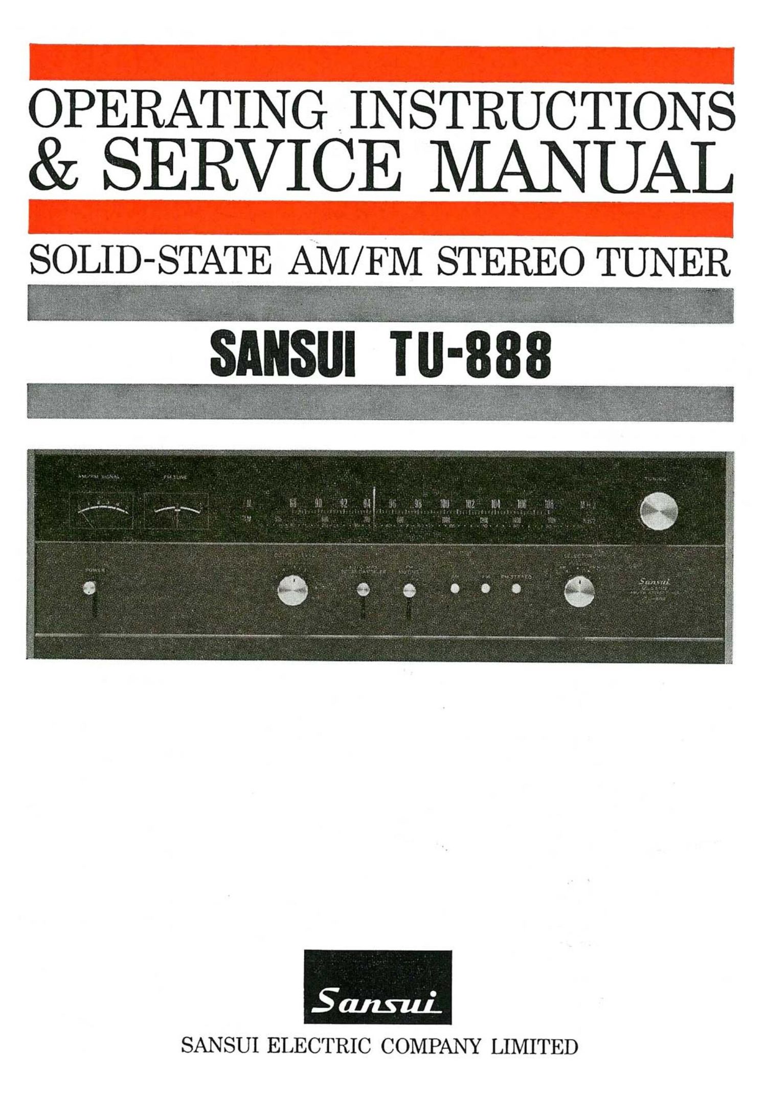
Sansui TU 888 Owners Manual

Extracted text from Sansui TU 888 Owners Manual (Ocr-read)


Page 2

Congratulations on joining the thousands of proud, satisfied owners of quality stereo com-
ponents from Sansui.

The TU-888 is the most advanced professional solid state AM/FM stereo tuner ever
manufactured by Sansui. As such, it incorporates the cream of our technology and long
experience with audio equipment. Particularly, the FM tuner section is designed with
the idea that FM broadcast is becoming an important program source which rates the
same consideration as tapes and disks.

The PM front end with PET and the IF amplifier stage with IC and a ceramic filter
together allow the tuner to offer unparalleled high sensitivity and stability, superior
separation and low distortion characteristics.

The TU-888 also incorporates a number of special provisions designed to insure quality
reception of F M stereo broadcasts. Such as auto MPX noise canceler and an LC type leak
filter with a sharp cutoff characteristic. And, of course, it comes complete with a full assort-
ment of accessory circuits. Among them: an FM antenna switch, muting level adjustor,
output level adjuster, two output terminals, and an AM/FM/ FM Stereo indicator.

The TU-888 features the refined dull black panels common to all TU series professional
tuners from Sansui. Together with the wide dial with twin tuning meters, linear dial
scale for the FM band and a selfiighting dial pointer, they make the tuner as smooth to
the eye as it is to the ear.

The TU-888 comes with the full confidence and guarantee of the manufacturer. It is now
up to you to read the contents of this manual carefully in order to operate it correctly and
obtain the maximum performance it is capable of offering for many years to come.

CONTENTS

OPERATIONS SECTION

SWITCHES AND CONTROLS ...................................................... 3, 4
CONNECTIONS ........................................................................ 5, 6
OPERATIONS .............................................................................. 7
MAINTENANCE ..................................................................... 7, 8, 9
SPECIFICATIONS ........................................................................ 9
CHARACTERISTICS .................................................................. 10
SERVICE SECTION

TROUBLESHOOTING CHART ................................................ 11, 12
DISASSEMBLY PROCEDURE / DIAL MECHANISM ........................ 13
BLOCK DIAGRAM ..................................................................... 14
ALIGNMENT ..................................................................... 15, 16, 17
PRINTED CIRCUIT BOARDS AND PARTS LIST ...18, 19, 20, 21, 22, 23, 24
ACCESSORIES ........................................................................... 25

OTHER PARTS AND THEIR POSITION ON CHASSIS ............... 25, 26