Sansui QRX 5001 Service Manual

This is the 32 pages manual for Sansui QRX 5001 Service Manual.
Read or download the pdf for free. If you want to contribute, please upload pdfs to audioservicemanuals.wetransfer.com.

Page: 1 / 32
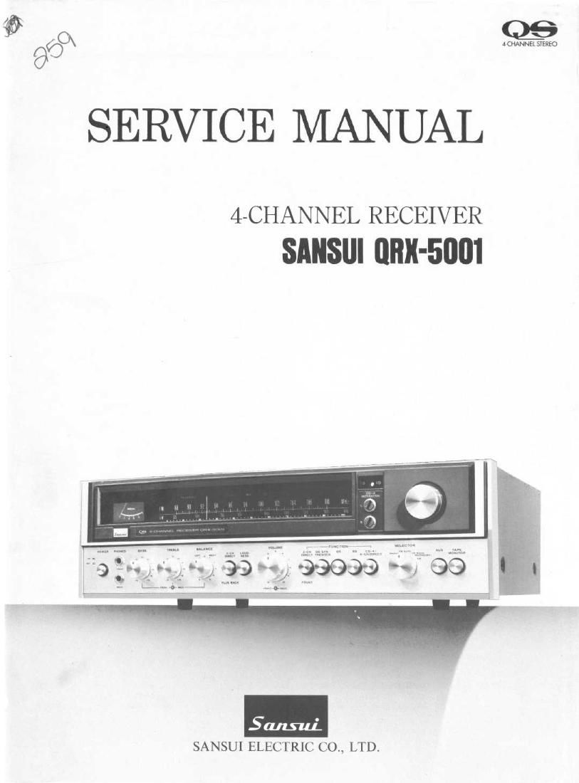
Sansui QRX 5001 Service Manual

Extracted text from Sansui QRX 5001 Service Manual (Ocr-read)


Page 2

This service manual is designed for service engineers to repair, adjust,

maintain and order the replacement parts of the QRX-5001 correctly.
When ordering the parts, use the stock number and parts name specific-
ally referring to the Parts Locations & Parts Lists.

For general usage and maintenance of the unit, please refer to the
Operating Instructions attached with the unit.

TABLE OF CONTENTS

Section T_itle P_age

1.
2.
3.

7.
8.

SPECIFICATIONS ................................................
BLOCK DIAGRAM .......... 3,
ALIGNMENTS ..................................... ,
3-1. Driver Circuit Board Adjustment ...............
3-2. FM IF Alignment .....................................
3-3. FM Dial Calibration, Mono Distortion and RF Alignment
3-4. MPX Alignment .......................................
3-5. AM IF, Dial Calibration and RF Alignment .......
TROUBLESHOOTING CHART .................
4-1. Troubleshooting on Audio Section .......
4-2. Troubleshooting on Tuner Section .............. ..
PARTS LOCATIONS AND PARTS LISTS .......................... 11
5-1. F-1506 Tuner Circuit Board ............................ 11, 12, 13
5-2. F-2084~1 Vario-Matrix Circuit Board ........................ 13, 14
5-3. F-2048 Vario-Matrix Circuit Board .......................... 15. 16
5-4. F-2454 Power Supply Circuit Board ............................ 17
5-5. F-2451 Main Circuit Board .................................... 18
5-6, F~2450 Tone Control Circuit Board ...........
5-7. F-2085 Equalizr & CD-4 Main Circuit Board. . .
5-8. F 2475 CD- 4 Sub- Channel Unit Circuit Board.
5- 9. Other Parts (Top Side) .........................
5- 10. Other Parts (Bottom Side) .....................
5-11. Other Parts (Front Side).

THREADING OF DIAL CORD
SCHEMATIC DIAGRAM .
PACKING LIST . .back cover
ACCESSORY PARTS LIST .............................. back cover

(DOWNNOIUIOIJINI

.9
..
o

Page 13

: Mylar Capacitor MLC. : Mica Capacitor
Electrolytic Capacitor 0.6. : Oil Canacltor

Bi~Polar Electrolytic Capacitor P.C. : Polystyrene Capacitor
: Ceramic Capacitar T.C : Tantalum Capacitor

: Carbon Resistor
Solid Resistor
. Cement Resistor
. : Metallized Film Resistor

PPM:

250735

77055551

0sc7n 11450
scum 23121312 ascsao 351141 2571552 111450 135430

Pam No. Stock No. Doscriptlon Position 2 E
C62 0669400 1561 50v c.c. 2 1; + 12 11 111 1
C53 0620361 360155 50v 12c. 2 a E W- " "56,
C54 0601107 0.01215 50v MC. 2 0 5° E C a a .

EC 2 1 z c a
C55 0512100 10711 16v EC. 20 1.1:..."
C56 0513479 4.7m 25v E.C. 10 Egg; 1 2 , 5 5 7 9 a
C57 0515109 1,111 1 D
C50 0515109 lyF] 5°V EC' 1.20
C59 0600826 0.003210 2 0
C60 0600326 0.0032211} 50" M'C' 20
C61 051210I 100m 16V E-C- 1:29 PamNo. Stock No. Ducrlpunn PoIItlon
C62 0601100 0.1;» 2D
C63 0601108 0.1/25] 5"" MC 20 R01; 0113562 5.610 1A
C70 0519101 1,21] 50v EC 20 R09 0113123 1210} MW 5.11. 1A
C71 0519101 1#F ' 20 R10 0113332 3.310 1A
C72 0650102 1000pr 50v c.c. 1A R11 0|l6822 8210 IA
C73 0510470 47,17 6.3V ac. 213 R12 0116222 2.2110} xw 02.15.12.) 13
C74 0519105 2.2215 50v E.C. 2c R13 01l6220 220 1A
C75 0513479 4.7/4F 25v ac. 1D R14 0113222 2.210 14.5
C76 0600157 0.01520] 50v MC 20 R15 0113102 110} %W 5.11. 18
C77 0600157 0.015211 ' 20 R16 0113471 4700 11;
C76 0513479 4.7;» 25v LC. 10 R17 0113221 2200 13
C79 0629001 6800pF 50v P.C. ID R18 0113392 3.910 13
(:01 0510221 22,00F 6.3V E.C. 2C R" 013'52 1.510 13
R20 0113101 1000 1 11
R02 0113394 39010 1A R21 0113152 1.310 1 11
R03 0113103 1010} %w 5.11. 1A R22 0113471 4700 %W 5.11. 11;
R04 0113104 10010 IA R23 0113601 6800 11;
0113101 1000 (35m (1 1 A R24 0113101 1000 13
R {0113151 1500 (351(41 (RH Kw 5"? 1 A R25 0113271 2700 13
R115 0113105 1M0} 11w 511 IA R26 0115152 1.510 113
R07 0113220 220 "4 " 1A R27 0113220 220 10
topagel3