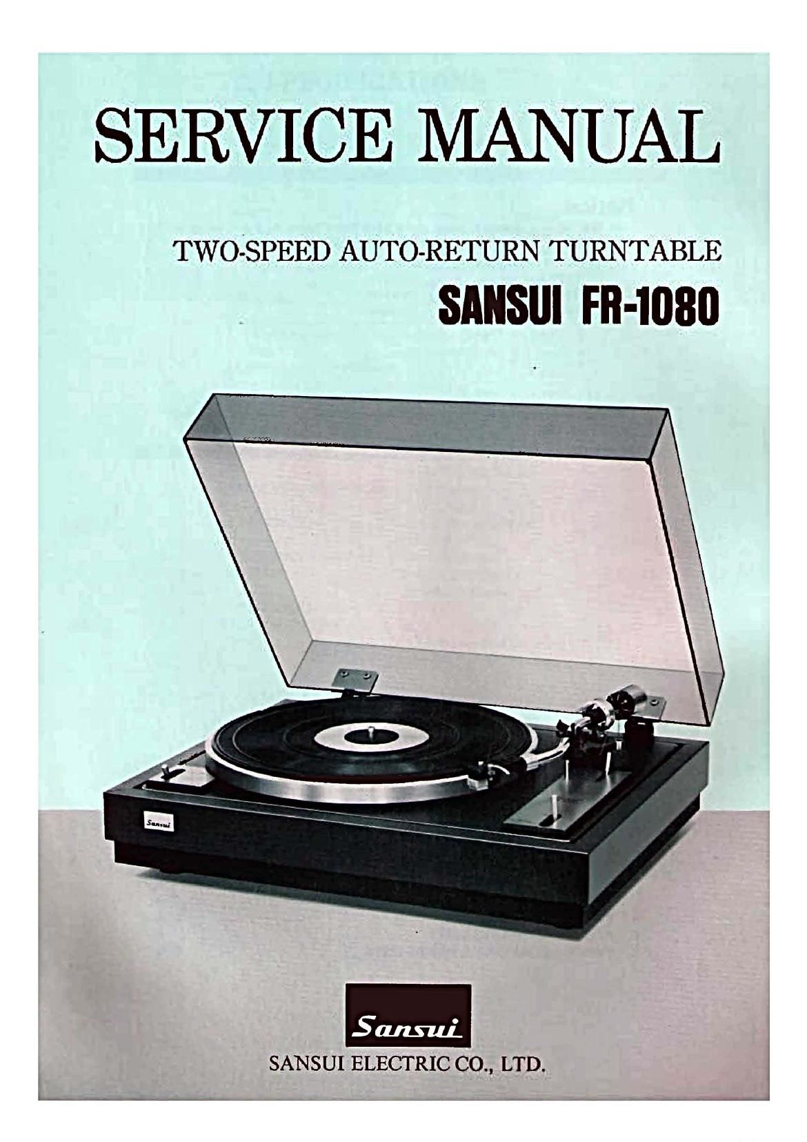
Sansui FR 1080 Service Manual
This is the 8 pages manual for Sansui FR 1080 Service Manual.
Read or download the pdf for free. If you want to contribute, please upload pdfs to audioservicemanuals.wetransfer.com.
Extracted text from Sansui FR 1080 Service Manual (Ocr-read)
Page 2
.lililillllllllillll|IIIll|illlilllllllliilllllIIIIHIIIIIIIIIIIIIIIIIIJlliliilllilllllllliIllllI|IllllillllilIllllllillllillill|llIIllillllllllllIIllllllllllllililllilllllillillllllllliiilllllilillIIIII
Notice:
In this service manual, some parts have three types,_A, B & C in same
parts No. as shown in Parts List. Each type can 'be identified from
Mark on the carton case as Fig. 1.
TYPE A .................. Ell-1080
TYPE B .................. FR-1080E
TYPE C: ................. FR-1080P '
Type Mark Fig. 1
' Type A No mark"
Type B Mark ®
Type C Mark (B ChuckJ-Jgfirm:
*When ordering parts, please use parts name and the stock No. referring
to Parts List. '
llllllllillll||lllililliiillllllllllll||l||||l||||IIIIIIIIIIIIIIIIIIIIIIIII||||Illllllllllilllllll|IIIIIilllilillllilllllllllllllllllll|illllllllillllllllll||Ill||llllIIIIIHIIIIIIIIIIIIIIIIIIIIIIIIIIII
TABLE OF CONTENTS
Section M P_ag_e
1. SPECIFICATIONS ................................................ 2
2. OPERATION OF AUTO MECHANISM ............................ 3
3. ADJUSTMENTS. . . . . . . . . ......................................... 3
3-1. Adjusting the Auto Return .................................. 3
3-2. Adjusting the Height of Tonearm Lifter ...................... 3
4. PACKING LIST .................................................. 4
5. ACCESSORY PARTS LIST ...................................... 4
6. PARTS LOCATIONS 8. PARTS LISTS .......................... 5, 6
Page 4
2. OPERATION OF AUTO
MECHANISM
1) in case that tonearm is left off the arm rest, the PU
plate will leave from micro-switch, then the turn-
table will be automatically switched ON so that the
platter will start rotating.
2) At the moment when the stylus reaches lead-out
groove, Auto-lever linked with PU plate starts push-
ing Reject-lever toward center of the platter.
3) As soon-as the stylus reaches lead-out groove, turn-
table spindle gears into main-gear so that the main-
gear starts rotating.
4) When the main gear starts rotating, the Auto-lever
will be pushed outward by see-saw lever located
under Return cam. -
Therefore,the tonearm will automatically return to
arm rest.
5) While playing a disk, tonearm lifter keeps down
gradually because the tip end of see-saw lever
moves down in sloped concave A (See Fig. 2-1) on
the backside of main gear.
On the other hand, when the tonearm is on its rest,
the lifter keeps up completely (6~12mm: space bet-
ween record and stylus) because the tip end of
see-saw lever is on the most shallow concave B.
Fig. 2-1
Main Gear
.>
Fig. 2-2
lead-out
groove
lead-o ver
groo ve
modulated groove
lead-in groo ve
3. ADJUSTMENTS
3-1. Adjusting the Auto Return
1) The adjusting screw in Fig. 3-1 is one to adjust the
position of Auto Return when stylus reaches lead-
out groove.
2) Make adjustment of the screw in such a way that
stylus lifts up automatically around the middle way
of lead-out groove.
Namely turn the adjusting screw clockwise is for
leading and counterclockwise is for lagging.
3) After adjusting the screw properly, check its opera-
tion a few times.
*Apply the locking paint in place to the screw after
adjustment.
Fig. 3-1
PU Plate Ass'y
Adjusting Screw
3-2. Adjusting the Height of Tonearm
Lifter
1) The adjusting screw in Fig. 3-2 is one to adjust the
height of tonearm lifter.
2) Place a disk (record) on turntable, then switch the
tonearm lifter lever to PLAY. if stylus does not come
down completely on a disk, turn the screw counter-
clockwise.
3) When tracing, switch tonearm lifter lever to LIFT.
If the stylus does not lift up completely from a disk,
turn the screw clockwise.
4) After adjustment of it, check its operation a few
times.
*Apply the locking paint in place to the screw after
adjustment.
Fig. 3-2
See-saw Lever
Adjusting Screw
Tonearm Lifter
[Lever Ass'y