Sansui AV 99 Service Manual

This is the 27 pages manual for Sansui AV 99 Service Manual.
Read or download the pdf for free. If you want to contribute, please upload pdfs to audioservicemanuals.wetransfer.com.

Page: 1 / 27
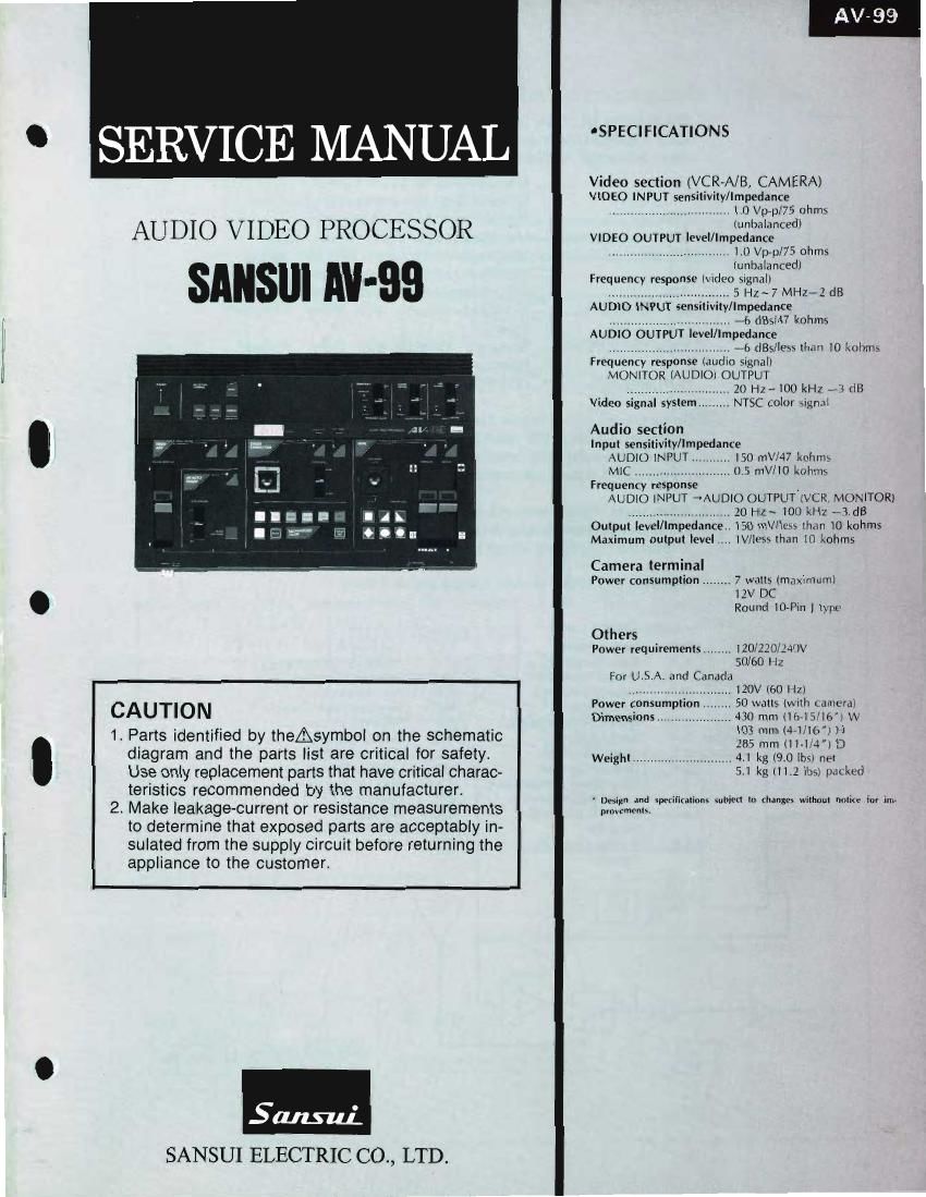
Sansui AV 99 Service Manual

Extracted text from Sansui AV 99 Service Manual (Ocr-read)


Page 1

OSPECIFICATIONS

Video section (VCR-A/B, CAMERA)
VIDEO INPUT sensitivity/Impedance

' SERVICE MANUAL

AUDIO VIDEO PROCESSOR VIDEO OUTPUT level/Im;:g:::ncem

............................... ID Vp-pl75 ohms

(unbalanced)
- Frequency response ivideo signal)
................................ 5 Hz~ 7 MHz~2 ("3

AUDIO INPUT sensit ty/lmpedance
................. 76 (185/47 kohms
AUDIO OUT UT level/Impedance
................................. if; (lBs/Iess than IO lmhrm
Frequency response (audio signal}
MONITOR (AUDIO) OUTPUT
20 Hz~ IOO kHZ >73 (t8
NTSC color signal

Video signal system

Audio section
Input sensitivity/Impedance
AUDIO INPUT.
MlC ..............
Frequency response .
AUDlO INPUT ->AUD|O OUTPUT (VCR. MONITOR)
............................. 10 Hz- 100 Ml), -3.dB
Output level/Impedance lSO mV/k'Ks than I0 kohms
Maximum output level IV/IeSs than 10 kohms

30 WV/47 knhms
0.3 mV/IO i\()l1II1S

Camera terminal

Power consumption ........ 7 watts lmoximuml
. IZV DC
Round ltMin J type
Others
Power requirements ........ 120/2202240V
50/60 H:
For U.S.A. and Canada

120V (60 Hz)

CAUTION B?::L§32§".T?TTT?," W:.:!:-:i2:':i
1. Parts identified by theAsymbol on the schematic £2: :12 my}; 0'-
diagram and the parts St are critical for safety. Weight ............................ 41 kg (9.0 [rm net
Use only replacement parts that have critical charac- 5.1 kg m .2 It»; pm Led.
teristics recommended by the manufacturer. _ .. _ , , , _
2, Make leakage-current or resistance measurements ' 35553313 Wham "W '" "W" ""m" "m" i" ""

to determine that exposed parts are acceptably in-
l suiated from the supply circuit before returning the
l appliance to the customer.

Sans-id.
SANSUI ELECTRIC CO., LTD.

Page 2

CAUTION

1. The symbols, UL, CSA, SA, BS, UK, EU, AS, XX and
XX-V on the parts list and the schematic diagram
mean followings respectively.

UL ............................... Manufactured for USA market.
(Underwriters Laboratories approved model.)
Manufactured for Canadian market.
Manufactured for South African market.
Manufactured for United Kingdom market.
Manufactured for European market.
Manufactured for Australian market.
Standard Version with inner Voltage
Selector.
XX-V .... Standard Version with Outer Voltage
Selector.
NON MARK ................ Common Parts.

XX < EXPORT>

2. Some printed circuit boards are not supplied as the assembled.
To separate these in this service manual, the stock Nos are not in-
dicated at the ends of the board names. However, the individual parts
on the circuit boards are provided by orders.

3. Since some of capacitors and resistors are omitted from parts lists
in this service manual, refer to the Common Parts List for capacitors
& resistors, which was issued on Februanj 1983.

4. Abbreviations in this service manual are as follows.

L, ~Abbreviations List ' Ti ,

C.R. : Carbon Resistor E.B.L. : Low Leak Bi-Poiar
S,R. : Solid Resistor Electrolytic Capacitor
Ce.R. : Cement Resistor Ta.C. : Tantalum Capacitor
MR : Metal Film Resistor F.C. : Film Capacitor

l F.R. : Fusing Resistor MP. : Metalized Paper Capacitor
N.I.R. : Non-Inilammable Resistor P.C. : Polystyrene Capacitor
A.Fi. :Array Resistor G.C, : Gimmic Capacitor
C.C. : Ceramic Capacitor A.C. : Array Capacitor
C.T. : Ceramic Capacitor, V.R. : Variable Resistor

Temperature Compensation S.V.R. : Semi Variable Resistor
E.C. : Electrolytic Capacitor SW. : Switch
E.L. : Low Leak Electrolytic Chip R, : Chip Resistor
Capacitor Chip C, : Chip Capacitor
EB, : Bi~Polar Electrolytic
Capacitor

1. BLOCK DIAGRAM

1-1. INPUT SELECTOR and COLOR CORRECTOR Section


rNRuT SELECTOR . L
, 7 VIDEO/iNT-SYNC
i|C14 _ SELECTOR
VCRVA
C 9 SYNC. SEP
l lIC1
u OK 25 '01 2 A VIDEO SIG or COMPOSITE SYNC C2
AY FLl
PL 3-0 I/ 1 TA7357
VCR»B 7 3 WT SYNC GEN (Generator) DELAY
@g 24
1 nos
05:; 05 MSMszsa
r2 '4
102
P 4
SELECTOR age r012 REF FREQ
CAMERA SELECTOR
REVERE R B F DC LEVEL
lCA O Chg sre OET 3.58MHZ
fl nLDi , 4 m REF SIG «132
-l i-< l06
SELECTOR 1 PHASE
CONTROL H may, (i) SHiFTER PHASE
, Page 5 SHIFTER
nIce 033
0532m35 r 34 FILTER
,La AMP
+ B 4
we SiG rVRS
SEP (TRAP) V(Luminance)-SiG REF ad]. PICTURE
EFFECTOR
(01 m '03 ros-e 04
Page 4
CLAMP SYNC Page 4
COLOR ,02 SUPPRESSER
are
(3 SMHZ) '07 PHASE
P.C.P . SHIFTER
4 rVRI COLOR CONTROLLER
r011 , ,///
v. i
S G r08 I .
COLOR
DELAv CORRECTOR
rLFi a
'VF'ZCOLOR l riC3 il-
LEVEL CONTROL BA7230LS " (0
REF SIG (FREE RAN) rQiO 5 T
W CONTROL 9
0
I DELAY 3 B'F'P'A
20 2 Page 5
W -F2 1 +- P OF
CONTROL
(5 32 SIGNAL
WiDE R I sw
L
" 08 NORROWI '015
WlDE I COLOR CORRECTOR-SiG
p
age a , MIXING
('5 nlC4 709130 nLDi7 C
0528 ~ 31 i5 I
5389:? Fr, r014 r015 i
COLOR CORRECTOH- , 2 m / l/ Page 3
I06 ENHANCER SELECTOR rL1 CLAMP
n COLOR CORRECTOR ON a i ~ :5 ,ng
(by L i
P CP
Page 3 Page 5

Page 3

1_2 AUTO FADER and ENHANCER Section 1-3. BACKGROUND COLOR and WIPE PATTERN Generator Section


O o
PROCESSOR *
s C PULSE PROCESSOR SVNzAzrgtV'SZER IN 2 "C17 \ VCREA OUTPUT
H, YN - L 4 I V
C _ BF P I028 PHASE SHIFTER > C i" 106 TED
BF P p e 2 I 1VR9 Page 3 I ,.
Page 2 IIC4 » N am a9 G m I92 I030 - 3 @) VCR-B OUTPUT
COMP I08- 10 2 (Page 5) VCR-B C)
b SYNC (Page 5) g B F P my COLOR BAR PROCESSOR CAMERA
, . » 2 a4
, BINARY IICTa MONIT R EFF
IVR10 Jog CLAMP Page 3 M V COUNTER 2 4 O ECT
SYN? d Nam 61)- e CB7 u I 3 :7T «fix fig)
L e a V \ /
9V ' y 3 __ nc39H I VCRLA Page 2
E P Pa e 5 L 2 3 3; CAMERA
Page 4 V B P g . 9 - 2 -4 + my MONITOR DIRECT
BACK GROUND COMP. SVNC V B PJH B P CLAMP
COLOR SIG (SUB CAR,
IC1 (C45 46 r029 CANCEL) Page 2
1 L 7
CI DELAY JIC11 5 ' JIcze . 3 mm L 3 4 F VIDEO SIG
-o I 0 . 1-110 0/ 5 Level am, MODULATOR
O17 rt H
V er024 ILF1 I 19 I026 -o_ I5 3 m V2 9 Page 4 4 A 6 RED ,3 7 / (COLOR)!
I2 I O I 9 I 5
FNHAN F-m rICs rVR7 r028 5 ,
Page 2 VVW 2 V B P, OFF I 5 9 a GREEN M L250 41 Page 3
' I II 4 I ' r0
LeveI £8225 CLAMP H B P page 2 MC rL2 rlC5 5 3
Page 4 am Page 5 _ 2 V2 BLUE V5 3 NJM1372
VP _1023 Cl?) >15 591,026 , 77, . V6 rVRG \ r026 v ggfigggcéum
BACK GROUND '
CLAMP POL/3"}: COLOR PROCESSER If I: " \ (mm 5'5)
IL -4 RG B
AUTO FADER i012 - PCP P CP .L 1024 ® ENHANCER ENCODER RV r027 CLAMP TLF3 DELAY
ON 6 5 5 L Lave! ad].
NJMI496D Page 2 P c P '_
BACK GROUND
4 IICS 5 ,7; H COLOR CONTROL 2" V-SIG
l L5 CLAMP "€36 F to PULSE PROCESSOR
'9 ad]. _)O43_ 1042 9 2 3 (Page 5)
a 1010 \
l , 4 C40 H SYNC VBPA
pa 9 4 m I2 W|PE PATTERN GENERATOR
9 BACK GROUND vRe L
Q),- COLOR SIG IIC12 IIC12 I (313 now
025 "cm "026 IIC32 L4 ,2
12 H. POS C ' EV1|CZ7
A [ICIO V014 fl nICBIRZPOZT bx PAT V POSL@\ 0
CLAMP l V95 032447, 38~42 3 7 9
'0 LeveI f w REF
ion 5 I09 adI BACK GROUND COLOR SELECTOR VVFHG SIG, PRO
V _ _ , _ V" i ?
NJMI4QSD 1VR52 7 . ,
V , ENHANCER , 7 s PAT "CM IC31
253:5 VOLUME IVR22 C -
CONSTANT 7 , -B POSITIONER I
- IVR17 "030 _
VOLTAGE (FLIPFLOD ENHANCER /, .. I a 9 6 . PAT 1.)
'2 JR. ' ' » II032 0313-23
/ i 2 PAT Ilcao ® a IIC34 35
, l [-1 .
103 A gllcau ' H P08 6 IIC15 L+- $3 nIca
' 5
VARIABLE #- ® éVéEESTgFTVERN
VOLTAGE I (Page 5)
Emma-E s A
IIczo IC2
IICI coMPALATOR LOGIC DRIVE V' P03 2 017 5 EPAT > 922 3515, 17
1'04 ~ 7 103 IVR24 w Egg? 3 0335, 37
HORIZONTAL
ONE SHOT L: 21 vapos COMPALATOR PAT iVRM WIPEART
M V g) 2 (:16 7 4 CONTROL SELECTOR
1064 0? ncza 029
u m ' IICS I05.6 65 032 COMPALATOR ncso H, P03 V P05 €30 WIPE
I028 2 nIC7 _o, 9 ON ®
I 0343 LAUTO FADER 7L , 031 9 C28 RT
ON/OFF 0344 < IN/OUT> , 5 7 -( ; L( f) QQA
» ,L 9 © ON 21AUTOI1*MANUAL . . 1VR23 "me 3&2,ng " REV®
J IIc7 O VERTICAL @_* pROCESSOR
A DER ® REMOTE
VRI N CAMERA PAusE Page 2
'FADER _UTO FADER -ONTROL Page 4 TermInal Page 3
DURATION