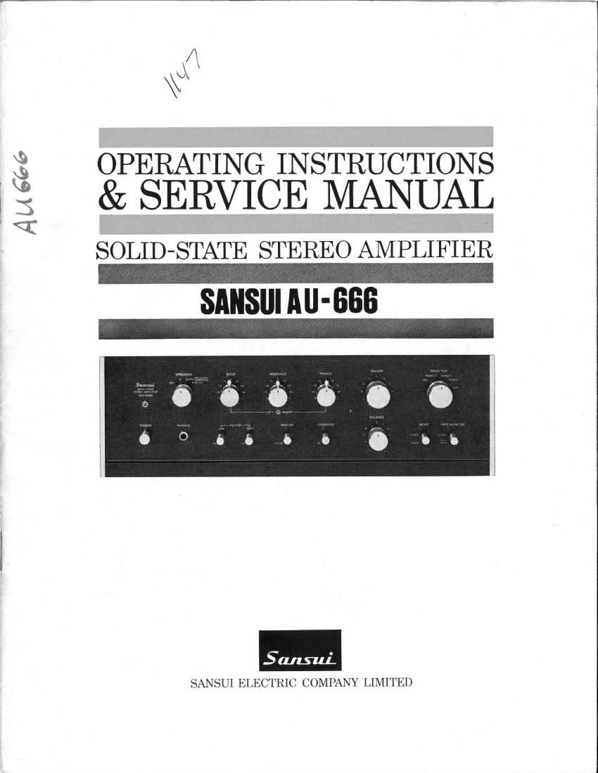
Sansui AU 666 Service Manual
This is the 17 pages manual for Sansui AU 666 Service Manual.
Read or download the pdf for free. If you want to contribute, please upload pdfs to audioservicemanuals.wetransfer.com.
Extracted text from Sansui AU 666 Service Manual (Ocr-read)
Page 1
A56,
(I
\\4\J
OPERATING INSTRUCTIONS
& SERVICE NIANUAL
SOLID-STATE STEREO AMPLIFIER
-
SANSIII All- 666
SANSUI ELECTRIC COMPANY LIMITED
Page 2
Tank you for selecting the Sansui AU-666 Solid-State Stereo
Amplifier, an excellent choice that will become more apparent
after years of rich stereo listening.
Sansui is known throughout the world for the unsurpassed qua-
lity of its audio equipment line, be it a control amplifier, a stereo
receiver, a speaker system, a turntable, a tape deck or a stereo
headset, and takes the greatest efforts to merit and maintain this
reputation.
The AU-666 is no exception. It features the refined dull black
panels common to all AU series professional control amplifiers
from Sansui, the direct-coupled complementary circuits in the
power amplifier section and the exclusive Triple Tone Controls in
the preamplifier section. Special provisions have also been made
to permit the amplifier to be built up into an electronic crossover
system and permit comparing such a system with a standard stereo
set up. This manual has been prepared to aid you in keeping the
AU-666 working perfectly. Please read the contents of this
manual carefully before installing or operating the amplifier. You
will then be able to enjoy the world's highest standards of sound
reproduction to the fullest.
CONTENTS
OPERATING INSTRUCTIONS
SWITCHES AND CONTROLS .................................... 3, 4
OPERATIONS .......................................................... 5, 6
-CONNECTING LOUDSPEAKERS
-RECORD PLAYING
-MICROPHONES
OPERATIONS .......................................................... 7, 8
-TUNER
-TAPE DECKS
ELECTRONIC CROSSOVER SYSTEM ....................... 9, 10
MAINTENANCE ................................................ 11, 12, 13
SPECIFICATIONS/ACCESSORIES ................................ 14
CHARACTERISTICS .............................................. 15, 16
SERVICE MANUAL
TROUBLESHOOTING CHART ................................ 17, 18
DISASSEMBLY PROCEDURE ...................................... 19
BLOCK DIAGRAM ...................................................... 20
TEST POINTS ............................................................ 21
ALIGNMENT ............................................................ 22
PRINTED CIRCUIT BOARDS AND PARTS LIST
...................................... 23, 24, 25, 26, 27, 28
OTHER PARTS AND THEIR POSITION ON CHASSIS .. 29, 30
Page 6
Electronic Crossover System
The electronic crossover system is said to he the
best hi-li sound reproduction method available,
featuring the following advantages:
1. Since the tweeters, midranges and woofers have
their onn amplifier, any speakers of different im-
pedance and elliciency can be used for stereo ar-
rangement.
2. This system has better filter characteristics than
the conventional LC crossover network. Yon can
determine the, optimum crossover points for the
speakers used.
3. Since there is no component between the ampli-
fier and speaker, the damping factor of the amplifier
[is not affected and it is directly coupled to the
speaker.
4. This system allows use of the power amplifiers
effecth ely and efficiently. For instance, a big-power
amplilier can be used for woofers, and ones with
good characteristics for midranges and tweeters.
You can select the amplifiers suitable for each of
the woofers, midranges and tweeters.
Connection
The AIF-Gtiiis preamp and main amplifier sections
can be used separately by simply removing a pair
of connectors from the PRE OUTPUT and MAIN
INPI'T jacks on the rear panel. This feature en-
ables you to use the AUvfititi as two separate com-
ponents of the Electronic Crossover System in the
following manner:
1. Set the SPEAKERS switch to SYSTEIVI B.
2. Turn the POWER switch off and then remove
the two connectors from the PRE OUTPUT and
lVIAIN INPUT jacks.
3. Connect an electronic crossover unit (Sansui
CD-5) t0 the FREE OUTPUT jacks.
4. Connect the low-frequency output of the electro-
nic crossover unit to the MAIN INPUT jacks on the
ALI-666.
5. Connect the right and left woofers to the SXS-
TEM B terminals on the AI7-666.
6. Connect the mid-frequency output of the elec-
tronic crossover unit to the inputs of the second
separate power amplifier (Sansui BA-90), and the
right and left midrange speakers to the said power
amplifier.
7. Connect the high-frequency output of the elec-
tronic crossover unit to the inputs of the third sepa-
rate power amplifier (Sansui BIA-90), and the right
and left tweeters to the said power amplifier.
NOTES:
1. You can connect a stereo pair of lull-range
spekers to the SYSI M A terminals in addition to
the woofers connected to the SYSTEM B and di-
rectly compare the sound of the Electronic Cros-
sover System with that of the ordinary stereo ar-
rangement by turning the SPEAKERS switch bet-
ween the SYSTEM A and B positions.
2. The connection of an additional pre-amplitier to
the MAIN INPUT jacks cuts off all front panel
switches and controls except the SPEAKERS switch.
Thus, to adjust the tone and volume, operate the
controls of the additional pre-amplificr connected to
the AU-(ititi. When an additional power amplifier
is connected to the PRE OUTPUT jacks, the tone
and volume can be adjusted by the controls of the
Alf-(366.
PRE-AMP
OUTPUTS
RECORD PLAYER
STANDARD
SYSTEM
ELECTRONIC
CROSSOVER UNIT
LEFT SPEAKER RIGHT SPEAKER
LEFT CHANNEL
RIGHT CHANN EL
AN EXAMPLE OF CONNEC-
TIONS FOR ELECTRONIC
CROSSOVER SYSTEM
POWER AMP OUTPUTS 1
FOR WOOFERS
POWER AMP
INPUTS FOR
WOOFER
POWER AMP FOR
MIDRANGES
POWER AMP FOR TWEETERS
_1o_
TWEETER
MIDRANGE
WOOFER
LEFT SPEAKER
TWEETER
MIDRANGE
WOOFER
RIGHT SPEAKER