Rotel RX 880 OM

This is the 7 pages manual for Rotel RX 880 OM.
Read or download the pdf for free. If you want to contribute, please upload pdfs to audioservicemanuals.wetransfer.com.

Page: 1 / 7
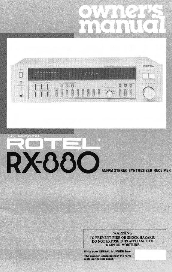
Rotel RX 880 OM

Extracted text from Rotel RX 880 OM (Ocr-read)


Page 2

INTRODUCTION

We at Rotel want to thank you tor purchasing
our audio product.

Rotel audio products are designed to use the
latest electronic technology, and they incorpo
rate our long experience as a specialist manulac-
turer ot audio equipment. We are confident
that you will tind satislaction in the high
quality sound and top performance. and that
you will Iind pleasure in the tunctional beauty
achieved through humanvengineering concept.
Betore starting operation. please read this
instruction manual thoroughly and ecouaint
yoursell with the proper mode or using the unit
and all its connections

We hope you will enjoy topnotch pertormance
lot many years to come.

BEFORE ENJOVMENTI
POWER SUPPLY

Follow the instructions below lot maximum
selety:
'I. Use a wall outlet or Rotel fill-800 lor

now-r supply
Be sure to connect the AC line card directly to
a household wall outlet or Rotel Bil-800. and
not to an aux ary outlet on another compo-
nent. Be certain that the outlet voltage matches
the electrical rating ol the unit. tound on the
rear panel name plate.
2. Connecting and rimming Ac cod
Be sure to connect or disconnect the AC line
cord only atter turning oil the power switch to
prevent possible shock noise or damage to
the speakers.
3. Ventilate the unit well
Never block any ventilation holes at the top
and bottom at the unit. as sure also to provide
ample ventilation space around the unit. Poor
ventilation may result In damage due to new
sive heat.
I. Do not open the claim
In order to avoid electric shock or damage to
the component. never open the cabinet. It a
loreign obhct Ialls inside the unit by mlstelae,
turn the power oil. disconnect the wall plug,
and consult a ouelilied electrician or your
dealer.
5. lnetalletion
Be sure to place the unit in a level and tlet place
where it is tree lrom humidity, vibration, high
temperature and not exposed to direct sunlight.
Ba carerul not to place the uni in a highly
enclosed place such as near a wall or on a
bookshelt. A poor ventiletlpn will cause unde»
siraole etlects to the unit.
6. Movingtheunlt
When transporting. remove the Ac cord trom
the wall outlet and all other connected cords on
the rear panel to prevent wire breakage and
short circuits.
7. ll theunlt gets not
It the unit should get wet. immediately dlsconv
nect the AC cord. and consult your dealer or a
ouelilied electrician.
s. etching and melntenence
Do not use chemicals such es benalne or thin-
ners on the tront panel. Always use a salt. dry
doth to clean the unit.
9. Owners mutual
Keep the owner's manual near the unit. and
record the se' I number (found on the rear
panel) on the cover.

SPEAKERS

Use speaker systems tnnth impedance ratings of
346 ohms Belore hooking up your speaker
system. be sure to check its impedance, which
should be indicated either on the back at
the speaker. or in the speaker instruction men-
IJII.

HOOKING UP SPEAKERS

On the rear panel at the nx-eao a e two sets
or speaker terminals. "A" and B", to which
two speaker systems may be connected. Con~
nect the speaker leads ot the rigtt-hand speaker
to terminals Fl" of "A" (or "8"). and the
speaker leads ot the I it hand speaker to ter-
minels " " . Make sure that the
4 speaker lead is connected to the "t" ter-
and the "-" leod to the " " terminal.
Strip 1.0:! (313") ol the polyvinyl chloride
insulation trom the end at each speaker lead.
Twist the exposed strands tightly. and secute
the end with a touch ot solder.

The terminals are the push-Mart type. Insert
the end or the lead into the hole mile pushing
on the button. Then release the button; the
hole will close and the cord is lirmly tixed.

ANTENNA INSTALLATION AND
CONNECTION

I FM Antenna

Proper installation at antenna is the key to
smooth signal reception. To install the attached
Tsheoe indoor antenna. stretch ll taut and
secure Mrilonully dong I all or the lilto
in a location where signal reception rs optimal.
Securely connect the antenna to FM antenna
terminals marked 300" on the rear panel.
ll outdoor type FM antenna is installed. the
Tvshmo antenna is not necessary. For proper
use ol your outdoor FM entenne, tollow the
instructions below.

1. Be sure to select the most appropriate
type at antenna tor the slytal reception condi-
tions in your area.

2. A 75ohrn coaxial cable is recommended
in connecting the antenna to the unit.

3. Set the antenna in a post
possible it btsildinw. mount ns or other
obstructions nearby altect reception.

d. The 75ohm coaxial antenna cable
should be properly hooked up to the designated
antenna terminals on the rear penal: Locate the
terminals labeled "2751: Connect the center
conductor ol the cable to the Iett-hettd ter-
minal. and connect the ouur braided conductor
ol the cable to the right-hand terminal (marked
"GND").

Note: The terminals are the push-insert type.
Insert the end ol the lead into the hole while
pushing on the button. Then release the button;
the hole will closo and the cord is ltrmly titted.

I AM Antenna

Erect the AM lerrrte bar antenna provided on
the rear panel. It you install outdoor AM

antenna. connect the antenna lead wire to the
antenna terminal marked "AM.

CONNECTING COMPONENTS

Connect all necessary audio components to the
rear panel or the unit, using RCA pin cords. See
the illustration tor properly completed com
muons. When connecting RCA pin cords, be
sure that L (lettl and R (right) markings on
each component are matched correctly. Cont
nect the grounding wire at the turntable to the
terminal marked GND en the receiver.

Note: The terminals on the rear panel marked
TUNEFI OUT prostrce signal from the tuner
section. These terminals are used when operat-
ing the unit in conjunction with the ROTEL
Remote Control Center RRABOO.

The rear panel oi the untt is provided wrth a
socket tor connecting the Hotel Remote
Control Center RREOO. which allows
wireless-remotecontrol ol the unit.

EXCLUSIVE NOTE FOR U.K.

It your unit comes with a 2-core cable
without a plug. make certain live and
neutral leads are contacted to the proper
tetmlnels. Check that the terminals are
screwed down lirmly end no loose strands
of wire are present.

IMPORTANT: The wires in this mains lead
are coloured in accordance with the tollove

lug com:
BLUE: NEUTRAL
BROWN: LIVE

As the colours of the wires in the mains lead
at this apparatus may not correspond with
the coloured markings identifying the
terminals in your plug proceed as rollom
The wire which is coloured BLUE must be
connected to the terminal which is marked
with the letter N or coloured BLUE or
BLACK. The wire which is coloured
BROWN must be connected to the terminal
which is marked with the letter L or colour»
ed BROWN or RED.